Fuses protect your system from catching on fire in the case of mishaps such as a wire rubbing through
Quick note before we get started. This is just one part of an overarching “How to Install a DIY Camper Van Electrical System” series. If you’ve just stumbled on this article directly without seeing that, there are likely some things we’ve already covered. If you want to check out that step by step guide, you can do that here: https://www.explorist.life/diy-campervan-solar
Also, we have solar wiring diagrams that are a complete, A to Z solution for teaching you exactly what parts go where, what size wires to use, fuse size recommendations, wire lug sizes, and all kind of other stuff to help save you time and frustration. You can check that out here: https://www.explorist.life/solarwiringdiagrams/
How to Size Fuses
The goal for sizing fuses is to determine a fuse size that will allow the device to function properly but also protect the wire that is supplying power to the device as well as staying below the short circuit current rating of the device (if available).
Use the Manufacturers Recommendation
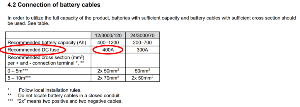
The first and best way to find the recommended fuse size is to use the manufacturers recommendation noted in the user manual of the device that you’re wiring. For example; the Victron Multiplus 3k 12V recommends a 400A fuse right there on pg 8 of the user manual.

When the manufacturer of a device makes a fuse sizing recommendation, it’s best to follow that recommendation unless there’s another external reason to do otherwise (code conflict, local regulations, poor user manual translation, etc)
Fuse Sizing Calculation
If there is no manufacturer recommendation for fuse sizing; use the following formula to determine a proper fuse size:
Continuous Amperage of Device * 1.2 = Recommended Fuse Size
Note: The 1.2 Multiplication factor is simply 120% of the continuous amperage of the device to allow the device to function as designed without too much overhead to make fuse sizing difficult. This is a rule-of-thumb and not a code/standard.
Tip: You’ll likely have to round the Recommended Fuse Size to the nearest available fuse size. Round down provided that the recommended fuse size does not fall below the continuous amperage of the device. Round up provided that the recommend fuse size does not rise above 150% of the max ampacity of the wire.
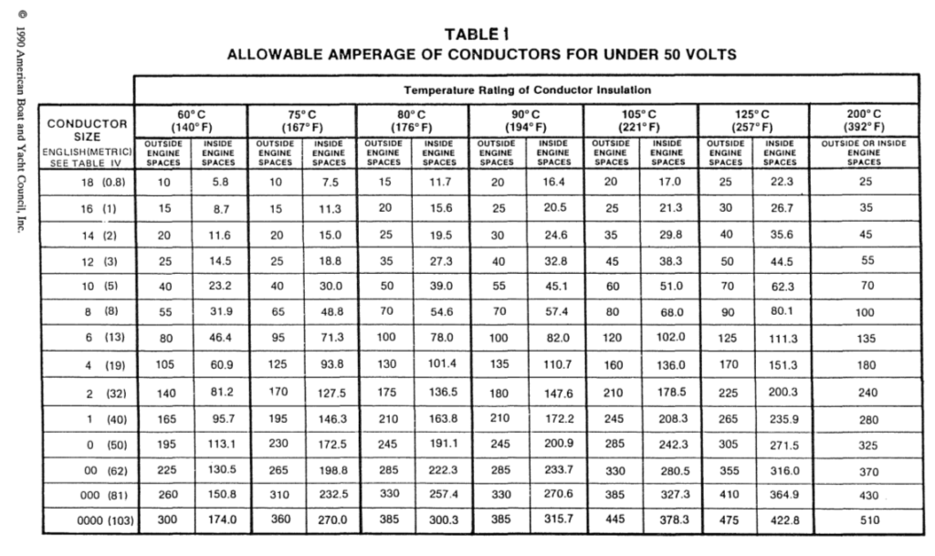
IMPORTANT: You must cross-reference this ‘recommended fuse size’ with the maximum ampacity of the wire you are using and verify that the recommended fuse size does not exceed 150% of the max ampacity of the wire you are using.

Here is a calculator that we’ve made to help:
Now that you know how to size the fuses in your DIY Camper Van electrical system, it’s time to put everything you’ve learned to work.
Everything that you are learning here is put to use in our FREE Solar Wiring Diagrams. If you haven’t yet, check them out as they are a complete solution for a camper van electrical system. Check them out here: https://www.explorist.life/solarwiringdiagrams/
Remember, this is just one part of a full camper van electrical educational series. To see all of the individual guides, click here: https://www.explorist.life/diy-campervan-solar


41 Responses
All your diagrams recommend ANL on the battery bank, but numerous internet people recommend Class T on the battery because of the short circuit rating. Any comments on ANL vs Class T and why you recommend ANL? Thanks
Class T is the better choice, but has been pretty much unavailable since 2019. At the moment, at our best estimate, there are only 50-something class T fuses for sale in the entire USA at the moment, none of which are actually available for purchase by individuals who aren’t professional installers.
Dear Sir,
We’ve supplied complete systems for a number of clients including schematics, BOM, and tech support.
We’ve just done a unique little job with 12KW of LiFePO4 storage in 180Ah batteries.
We have a 3kw pure sine wave inverter/charger. We have fusing, disconnect and power meters.
What we also have is a 300A ANL fuse in the factory housing
that has MELTED! We can say definitively that we have never drawn more than 2.2Kw continuous with only 600W motor loads started sequentially. My point, of course being, the fuse block should NOT be “melting”. Additionally, as the 300A fuse has remained intact, it seems clear that the current is not at issue.
We feed ALL components with 4/0 wire and heavy guage copper lugs which are crimped in our hydraulic crimper. Our wiring is overkill as the total wire run is under 10 feet round trip.
We have no issues elsewhere with hot wires or poor connections. Just the fuse block. Is it possible that the run of the mill Amazon units are not built properly? Is there a trustworthy CSA, ETL, UL certified ANL that we can trust to handle the current? We done 3kw systems before and never have we had this issue.
It is, of course, not beyond reason that we have apoor crimp hat is generating resistance and thus heat, and of course I will check this when I visit the site. However, all our fittings are built slowly and carefully and we’ve never had an issue. If our fittings check out, then I’m hoping you may have some ideas or suggestions for us.
Sincerely,
David
I have indeed had many issues with ‘run of the mill Amazon brand fuses’ melting. So much so that I’ve made a specific announcement and blog post addressing it here: https://www.explorist.life/best-fuses-fuse-holders-for-a-diy-camper-electrical-install/ For 3k 12V inverters, I recommend these Blue Sea Fuse Holders: https://shop.explorist.life/shop/all-products/fuses-breakers/anl-fuses-fuse-holders/anl-fuse-holders/anl-fuse-holder-with-insulating-cover-35-to-750a/ and these Blue Sea Fuses: https://shop.explorist.life/shop/all-products/fuses-breakers/anl-fuses-fuse-holders/anl-fuses/400a-anl-fuse/
Looking over the wire size chart and noted 4/0 has a max Amp rating of 444amps with a recomended fuse size of 556amps.
Seen many use 4/0 parallel jumpers for 4 Battleborn 100ah batteries.
However, 4 paralleled batteries are rated to 400amps with a 800amp surge for up to 30 seconds. Seems recomended fuse here will blow on each surge.
What am I confusing here?
GREAT question. I need to do a video over that. You are confusing the max potential output with the max ‘requested’. Even though the batteries ‘can’ put out that much, they will only put out what we ask them to. So… unless we ask them to put those 800A, the fuse will never blow.
Hi! Love these blogs and videos, wish I had seen them sooner!
I’m a little worried about my new system because the negative cane from my battery bank to my inverter charger heats up while no others across the bank or the positive do. I have a 12v system, 900 ah LiFePO4 battery bank to a GoPower IC 3000 inverter charger. 4/0 wire about 2 feet between them. The positive has a t fuse and shut off switch. The negative breaks at a bus bar to ground. I monitor my batteries using the charge controllers and the IC unit display, so there are no shuts or other breaks in the negative wire. Is there too much resistance on my bus bar? It’s a JQuad, 250 amp per stud. Is there another reason my negative will heat up more than any other connection?
Thank you!
Heat is usually a result of a poor connection. If you are using 4/0 wire, that is indeed big enough, but there may be a bad crimp or a loose lug to terminal connection. That’s where I would start. A loose connection ‘somewhere else’ in the system can cause heat on that wire as well; so check ALL connections.
I am building a House battery bank of 4 BB100s that I want to be able to expand to 6 total BB100s later. What fuse do I need now and later?
The fuse size wouldn’t change based on battery capacity.
If I have a 105ah battery with 2/0 wire, is a 250A ANL fuse what I need? Or do I need to decide on an inverter size too?
You need to know inverter size to determine the fuse size between the battery bank & distribution.
I have a 300ah battery bank with a 2000w inverter. For my system’s main fuse I have a 300a ANL fuse with 2/0 wire. Is this too small of a fuse? I’m worried that the fuse will blow with normal everyday use of the battery bank.
Clearly, I’m still learning how all of this works but I’m much further ahead than I was thanks to all of your info.
That is an appropriately sized fuse for that wire and load size.
Hi great blog! I am close to pull the trigger on a small system similar to the Regony budget system after buying the diagram for my solar ready cab over truck camper. When fusing wires I always thought with low volt DC that the AWG and length of run was all that was needed to size a fuse to protect the wiring. Are we also protecting the parts of the equipment like the bus, wire connectors and/or parts before the internal over current protections? In your diagram you have 80a fuse on 4awg wire and a 100a fuse on a 6awg wire this seams backwards to me unless we are protecting more than just the wires. Thanks for all you do to make this subject relatively easy to learn and fun to dork out on!
The fuse size is indeed sized to protect the wire UNLESS OTHERWISE SPECIFIED BY THE MANUFACTURER; which is the case in the scenario you brought up.
@Nate Yarbrough,
So what your saying is you don’t know why the MANUFACTURER would lower the amp rating for the wire. THANKS!
It usually has something to do with the internals of the component, but yes; I don’t know the specifics of each individual components internal workings nor was I involved in the research & development of said components, so I can’t say for certain. All I know is that if the manufacturer recommends a particular wire or fuse size AND that recommendation doesn’t go against electrical code (Things getting lost in translation for components with user manuals with poor English), it’s good enough for me.
Great information . Thank you for all the hours and energy you put into this . Best Regards from Florida . David
Great information for a new camper.
Please could you confirm if you multiply the amperage by 1.25 or 1.5? In the article you seem to use 1.5 and 1.25? Thanks
1.5
Hi Nate. Love all the info on here. Kinda lost right now. I need to wire my inverter to my batteries. From what I can tell on the installation sheet, is that I need 2/0 wire, and it calls for a 240 amp T-fuse no more than 7″ from the battery. Would I be able to use a 250 amp T-fuse, because I don’t see anywhere that has a 240 amp T-fuse. Thanks.
A 250A Fuse would be fine in your case.
Hi Nate,
This is all great information as I’m starting my project. I was just curious, I didn’t see you mention how you size the bus bars for the system. Do you have that somewhere in here?
I am using a Victron 12/3000/120, 3 Battleborn 100ah Lithium Batteries and the Victron 250/100 Solar Controller and Sterling B2B Charger.
Working on sizing the busbars now. The blog post & video on that will be out within 2 weeks.
Hey Nate, Very helpful site! I have one question, why is the resettable breaker in between the solar panel array and the charge controller rated at 15A? I’m planning to wire up 2 x 200W panels in series and for the future, I am counting on a max amperage of 10A coming from my panels. The wires will run for approximately 5-6meters. This means that the fuse size for that wire should be around 6ga with a recommended fuse of 100A, so why the 15A breaker? Thanks in advance.
So, a downfall of that chart is that it doesn’t take into account any voltages over 12V. When you wire your solar panels in series, you’ll be pushing nearly 40 volts. Wire size can decrease as voltage goes up, so…
I have a wire sizing calculator I use and I just plugged in your parameters and 9 amps at 38 volts (panels wired in series) allowing for a max of 3% voltage drop, 10 awg will be good until you get to 105 feet.
hi! I have 4 100watt renology solar panels and 3 100amp life po4 lithium batteries for my van conversion and don’t want to hook up getting energy from the motor or anything. I’m a bit confused on what fuse to get or if there’s anything I’ll need to change to have my van build work. Also, would a Aims Power PICOGLF20W48V120VR Pure Sine Inverter Charger, 2000 Watt Low Frequency Inverter, 6000 Watt Surge work with my Victron MultiPlus Compact 12/2000/80-50 120V VE.Bus Inverter Charger? I couldn’t find a two in one.. or do I even really need the aims power? I would really appreciate the help thank you!
Hey Sydnie! You won’t need both the AIMS unit and the Victron unit as they accomplish the same task. If you haven’t seen it yet, I think the wiring diagrams found on https://www.explorist.life/solarwiringdiagrams would help you out immensely.
Loved the post about fuses. I blew one recently using an air compressor on the vans 12v supply and it was a nightmare to fix. You’re post really helped me understand my requirements better. Our installer hadn’t even marked the connections correctly!
Your site is really inspirational. Three years into the journey already. Mine is only just starting out after quitting work last week to travel full time.
Awesome! Glad it’s been helpful!
I have 600 watts of panels on my Ford Transit , the MPPT 150/45 and the 12v 3000w 120 amp Victron. I am getting close to starting it up. I have 2 100amp Battle Born lithiums. I went with the 30 amp breaker from your diagram between the panels and the MPPT. Am I good with that?
As long as the panels are wired in series, yes.
@Thomas Tauer, what panels did you use? Also, is this a 148wb? Extended or regular? I have a 148wb regular length on order with Ford and I want to put 3x200watt panels, but will need to leave space for a Maxx fan too. I worry they won’t fit on the roof. THANKS!
Hello,
Thanks a lot for all the information you provide and for the way to calculate a lot of things.
The main solar components for my DIY van build project will be: 600W panels (2 X 300W), One 12V 400ah Lifep04 lithium battery, the 2000W Victron inverter charger, the Victron MPPT 100/50.
I am using the wiring diagram to adjust it for my needs based on your comprehensive e-book.
I am almost all right to identify nearly all the components I need, but from the wiring diagram, there is the 4 units of ANL 250 Amp fuses and the 50 Amp resettable breaker close to the MMPT, for which I can not find the way to calculate if the values from the wiring diagram will be good for my own setup.
Can you provide me more detail on the way to calculate the good values, or provide me the right numbers I should use?
Thanks in advance for your answer
Philippe
Of course! We have a blog post regarding how to size fuses here: https://www.explorist.life/what-size-fuses-to-use-for-a-diy-camper-electrical-setup/
Hi Nate,
It’s just amazing all the thing you have done in this website. A great great thank’s.
I have a question, easy one. I want to start with a 330watts solar panel and 2 x 100 Ah lithium batteries. But if one day I want more watts with an other solar panel ,I’m better to choose a 60 amp controller ?
Let me know if my thinking is good.
And again thank’s for all !
Thanks!
I would definitely go ahead and size the charge controller for future expansion if that’s your plan.
I’m using three Renology 160 Watt solar panels and four 100 Ah LI batteries. What needs to change on the diagram for me to successfully install this system?
You’ll only need to change the fuse between the solar panels, the charge controller, the wire between the charge controller and busbar, and the fuse between the charge controller and busbar. You can learn how to size all of that here:
https://www.explorist.life/how-to-choose-a-solar-charge-controller-for-your-camper/
https://www.explorist.life/what-wire-to-use-for-diy-camper-solar-system/
https://www.explorist.life/what-size-fuses-to-use-for-a-diy-camper-electrical-setup/