
A solar charge controller is a vital piece of a camper electrical system. It is installed between the solar array and the battery bank (or busbars, more often) and regulates the voltage and amperage of the solar array down to a level that is appropriate to charge a battery bank with.
Long story short, the charge controller is essentially a high powered voltage regulator.
Here are the three things we know about charging a battery bank from a solar array:
- The voltage and amperage of the solar array can be altered depending on how the array is wired.
- Batteries want to be charged at a very specific voltage.
- Solar arrays don’t put out a very specific voltage at all. They can be anywhere from 0 volts at night or upwards of 250V or more depending on the panels used and how the array is wired.
Q: So, how to we charge a battery bank that wants to be charged at a very specific voltage when our solar array puts out an incredibly variable voltage that is potentially much to high to charge a battery bank with?
A: We install a charge controller to regulate the high and variable voltage from the solar array down to a level that is more appropriate to charge a battery bank with. And here’s how it works:
What Does a Solar Charge Controller Do? – Video
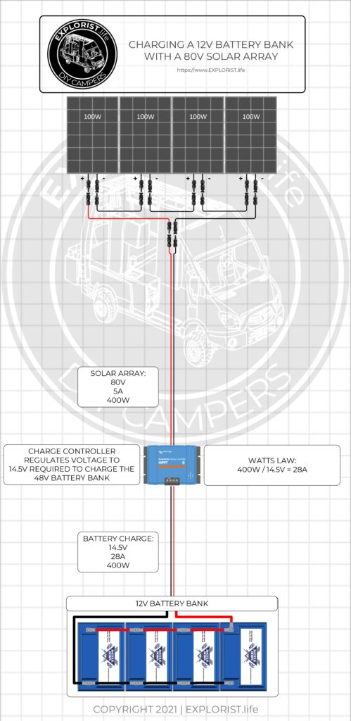
Charging a 12V Battery Bank with an 80V Solar Array
A solar array with 4 panels operating at 5A delivered at 20V each, wired with 4 panels in each series-string with 1 series-strings wired in parallel would result in a solar array that operates at 5A delivered at 80V to the charge controller for a total array wattage of 400W (Watts = Amps x Volts).
The Charge Controller will then convert the 80V from the solar array down to the 14.5V that it takes to charge a 12V Battery Bank. The 400W from the solar array is now being delivered to the battery bank at 14.5V and is therefore charging the battery bank at a rate of 28A (Watts/Volts=Amps).
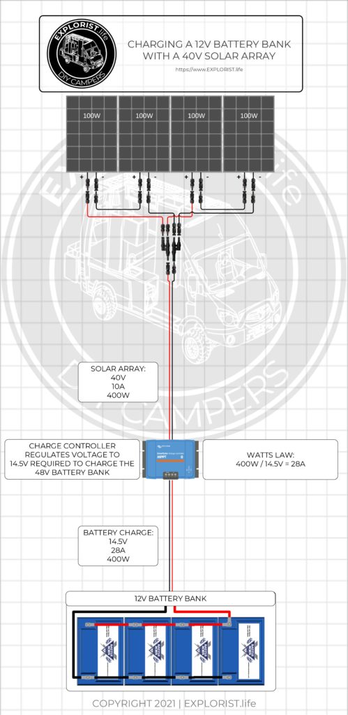
Charging a 12V Battery Bank with a 40V Battery Bank
A solar array with 4 panels operating at 5A delivered at 20V each, wired with 2 panels in each series-string with 2 series-strings wired in parallel would result in a solar array that operates at 10A delivered at 40V to the charge controller for a total array wattage of 400W (Watts = Amps x Volts).
The Charge Controller will then convert the 40V from the solar array down to the 14.5V that it takes to charge a 12V Battery Bank. The 400W from the solar array is now being delivered to the battery bank at 14.5V and is therefore charging the battery bank at a rate of 28A (Watts/Volts=Amps).
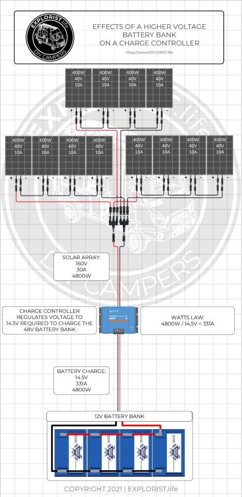
Effects of a Higher Voltage Battery Bank on the Charge Controller
A solar array with 12 panels operating at 10A delivered at 40V each, wired with 4 panels in each series-string with 3 series-strings wired in parallel would result in a solar array that operates at 30A delivered at 160V to the charge controller for a total array wattage of 4800W (Watts = Amps x Volts).
The Charge Controller will then convert the 160V from the solar array down to the 14.5V that it takes to charge a 12V Battery Bank. The 4800W from the solar array is now being delivered to the battery bank at 14.5V and is therefore charging the battery bank at a rate of 331A (Watts/Volts=Amps).
Now… This is really too many amps for a single charge controller to handle So… We could either use multiple charge controllers to handle this many watts coming from the array OR we could investigate using a higher voltage battery bank.
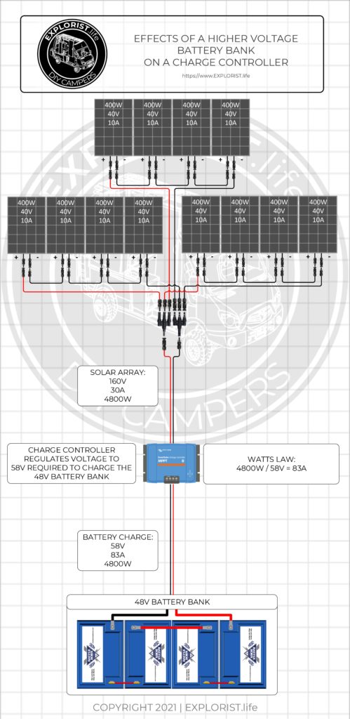
Understanding that the wattage from the solar array gets divided by the battery bank charging voltage to get the battery bank charging amps, we can see that as we increase the voltage of the battery bank, the amps charging the battery bank will decrease as the watts stay the same.
This would mean that the same array as earlier could be charged by a single 100A charge controller because the increased voltage of the battery bank as decreased the amperage demand even though the charging wattage remains the same.
A solar array with 12 panels operating at 10A delivered at 40V each, wired with 4 panels in each series-string with 3 series-strings wired in parallel would result in a solar array that operates at 30A delivered at 160V to the charge controller for a total array wattage of 4800W (Watts = Amps x Volts).
The Charge Controller will then convert the 160V from the solar array down to the 58V that it takes to charge a 48V Battery Bank. The 4800W from the solar array is now being delivered to the battery bank at 58V and is therefore charging the battery bank at a rate of 83A (Watts/Volts=Amps).
Charge Controller Operation Calculator
Here is a calculator that you can play around with that will show you how various array configurations and battery bank voltage interact with each other. (This calculator is NOT to be used for accurate sizing of a charge controller as it does not account for max voltages, amperages nor temperature compensation.)

10 Responses
Hey Thanks so much for all of the amazing and CLEAR information. I have been a carpenter for 35 years but electricity has always made me seize even without crossing wires. No more! Plus any excuse to buy tools makes me happy. Anyway my question is if I am adding a collapsible ground solar panel to augment my array can I use the same charge controller calculator? I am using your diagram which employs the availability of a large solar array but happen to have an extra victron 100/30 solar charge controller. Also curious how and where you put the connector for this externally on the transit. Perhaps I missed it in the videos. Thank you! Bev
The calculator doesn’t care where the panels are mounted. The external solar mount is covered in this video: https://youtu.be/E5q7_4FH4LQ
I have the Furrion 50A solar charge controller with a 165W Furrion monocrystalline panel. The price of additional panels are too expensive ($500 each) to add many to my fifth wheel. Suggestions for replacement panels that would give a better per watt price to use with this controller?
Mixing and matching solar panels rarely works properly. I’d recommend selling that panel and controller and start from scratch. Check out these various options I’ve put together: https://shop.explorist.life/product-category/all-products/camper-wiring-kits/solar-charging-wiring-kits/
Hi,
I’m looking for a 30amp shore power, 24V system. I already have 8/3.2 Lifepro4 cells that I’ll be linking together to equal the 24v battery bank with 280amp hour capacity. I want to buy one of your diagrams however they’re all 12v and the 30amp one that you have available is 1200 watts which I’m not sure if it will charge my battery bank, can you advise which diagram would be best for me or what components would need to be changed in order to make it al.l work for me?
I don’t have any diagrams available that meet your requirements, unfortunately. If you want to use my diagrams that’s great, but you’ll have to use the diagrams I have available because that’s how I recommend building these systems.
Nice video, very clear.
This is huge! I have a very small trailer (17’) and room for only 2 panels. Your diagrams, calculators, and written descriptions have provided me with the understanding and knowledge to create a safe and fully functional RV solar system based on our specific needs!!! Thank you Nate!
Craig R
Hey Nate! Many of us are finally starting to receive our Airstream Basecamp 20x trailers and I have a couple of questions that I think will help everyone out. It comes from the factory with 2×90 watt panels and a 100V 30amp MPPT controller but a lot of folks are adding 2 or 4 more 90 watt panels (for a total of 4 to 6 90 watt panels), would the 150V 35amp controller be needed for this and would it be enough?
The other big consideration, is how best to wire in an inverter. If I wire in an inverter, like say a Renogy pure sine wave inverter, is there a switch that can automatically disconnect the converter to prevent the dreaded inverter-converter charge loop? I’m assuming someone makes one but I’m not sure what it’s called. If expense is no matter, do you expect there’s an easy way to remove the factory converter and wire in a Victron inverter-charger all in one?
Thank you!
If you wire the panels in series parallel, you could get away with the smaller 100|30 or 100|50.
Sure! Here is a 30A RV retrofit diagram that would show you how to do that: https://www.explorist.life/30a-camper-inverter-with-solar-and-alternator-charging-wiring-diagram/ The OEM converter would simply be disconnected.