There are three ways to wire a solar panel array; series, parallel, and series-parallel. If the needs of your solar electrical system call for parallel wiring of your solar panels, this blog post will teach you how to wire your solar panel array in parallel.
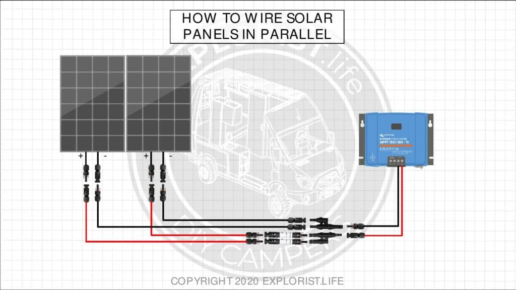
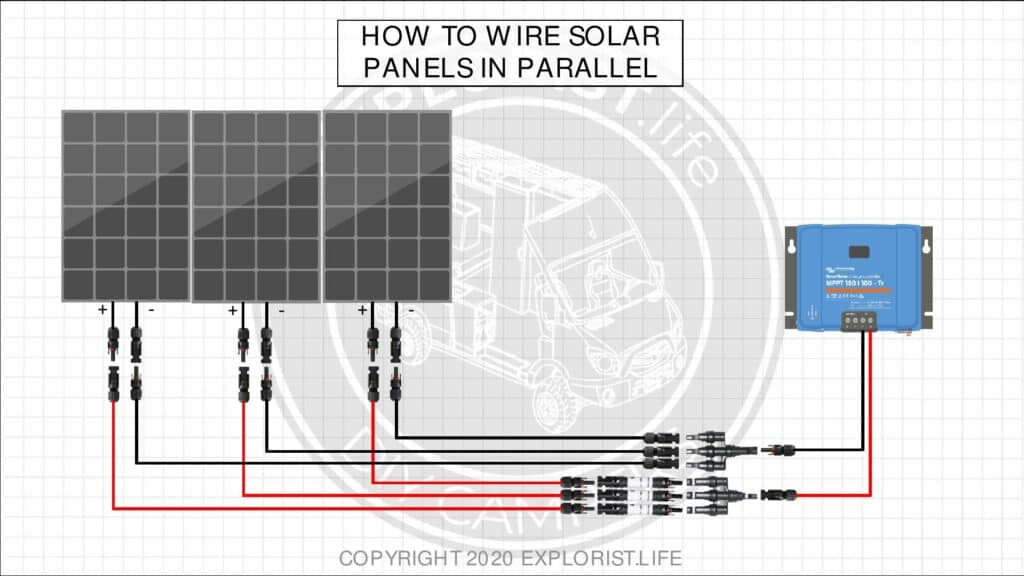
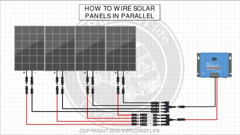
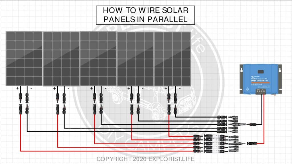
Wiring solar panels in parallel simply means combining all of the positive wires together into one wire that will go to the charge controller and combining all of the negative wires together into one wire that will go to the charge controller.
To combine the wires from the solar panels, you will need to use MC4 branch connectors.
- 2 to 1 MC4 Branch Connector
- 3 to 1 MC4 Branch Connector
- 4 to 1 MC4 Branch Connector
- 5 to 1 MC4 Branch Connector
Depending on your choice of panels, you may also need to incorporate fuses into your parallel wired solar panel array.
All of the diagrams below show a parallel wired solar panel array with fuses in their proper place. If your setup does not need fuses, simply ignore the fuses and connect the positive wires directly to the branch connector.
How to Wire Two Solar Panels in Parallel
How to Wire Three Solar Panels in Parallel
How to Wire Four Solar Panels in Parallel
How to Wire Five Solar Panels in Parallel

13 Responses
Hello Nate, great information. Jumping on the similar topic below. I have 6 ea. 200W panels that I was going to wire as 2S3P. Each series set would be 43.6v and 10.76a. When I parallel, these would be 32.28 amps. This would be just over the 3-way branch connector rating of 30 amps.
I was trying to maximize my amperage and stay with a good voltage.
Is there any other device I can use to keep max amperage with the 2S3P array? Or, will I need to change to a 3S2P array?
My MPPT is a 150/65 so I am good provided I don’t go total parallel and I will be fusing the panels.
Thank you!
Hey! We actually have a full solar array wiring kit available here that includes recommend wiring/fusing/etc for 6x200w panels: https://shop.explorist.life/product-category/all-products/camper-wiring-kits/solar-charging-wiring-kits/
Hi,
I plan on using 3, 200W, 12,7A panels in parallel because the Renogy MPPT only accepts max 25V.
Putting them all in parallel will get me to max 38A which is to much for the MC4 connectors.
But is it also possible to not use branch connectors and wire them all separate and straight to the MPPT?
This is a better way to set up 3x200w panels and is what I recommend. 3x 200W panels with a 25V max charge controller is the wrong tool for the job, so I’d recommend returning that and do this instead: https://shop.explorist.life/shop/all-products/camper-wiring-kits/solar-charging-wiring-kits/600w-solar-charging-wiring-kit-3x-200w-12v-battery-bank/
Hi Nate, I’m going to install one of your designs on the flybridge roof of my boat (2 panels, one string to start with and work up to 6-8 panels, two strings) and want to install the end product wiring size requirements at the start. My round trip wire run is about 80 feet with some constriction getting off the roof. Smallest wire size from panels to controller will be needed. Anticipating Renogy 160W (if they are still available) or Renogy 175W panels to Victron 100/50. I’m a bit confused however about where and when I should wire series or parallel or series/parallel with the branch connectors to minimize the wire size requirements getting off the roof. Can you offer suggestions or advice?
Thanks, Rodd Browne
You want your solar array voltage to be at LEAST 20V higher than your battery bank charging voltage and you solar array amperage under 30V so you can use MC4 connectors. To do this, you’ll have to do some form of series parallel to make this possible. Pure series would exceed the max solar input voltage of your 100/50.
Hey! I have three Renogy 100w panels that I am looking to wire in parrallel. Do you recommend adding fusing before my positive 3 to 1 branch connector? Thankyou!!!!
Those would, indeed, need to have fusing before the branch connector.
Do I need a double pole circuit breaker for both the positve (red) and neutral(black) cable going to the charger controller as you showed in one of your diagrams or can I just use an inline fuse on the positve cable to the MPPT? Thanks!
The dual pole disconnect as per my diagrams is in accordance with NEC 690.17 (B).
My GoPower 160W panels came with 10 AWG wire and MC4 connectors. When I combined the three panels, should I have used 8 AWG or 6 AWG to run the single combined line to the charge controller?
If the panels are wired in series, you can use 10 awg wire.
Thanks