
In this blog post, I am going to teach you how to wire a solar array disconnect, why you need one, and which one to use when installing a solar array into your camper electrical system.
A solar disconnect is not only convenient, but is also a code requirement. By the end of this blog post, you will know what disconnect to use, why you need to use one, and how to size the disconnect.
DIY Camper Solar Disconnect Parts List:
| Column A | Column B | Column C | ||
|---|---|---|---|---|
| #colspan# | #colspan# | |||
| This parts list contains the parts necessary to wire a dual pole solar disconnect between the solar array and charge controller of your DIY camper solar electrical system. | #colspan# | #colspan# | ||
| Product | Qty | Link | ||
| Solar Disconnect Breaker | 1 | |||
| Din Rail Breaker Box | 1 | |||
| 10 AWG Red Wire | 30 | |||
| 10 AWG Black Wire | 30 | |||
| 3/4" Truss Head Screws | 12 | |||
| Cable Clamps | 4 | |||
| The following parts are not 100% necessary, but make for an incredibly clean and professional installation: | #colspan# | #colspan# | ||
| Wire Duct | 1 | |||
| 10 AWG Ferrule | 4 | |||
| 1/4" Red Heat Shrink | 2 | |||
| 1/4" Black Heat Shrink | 2 | |||
| Din Rail End Stopper Block | 2 | |||
| #colspan# | #colspan# | |||
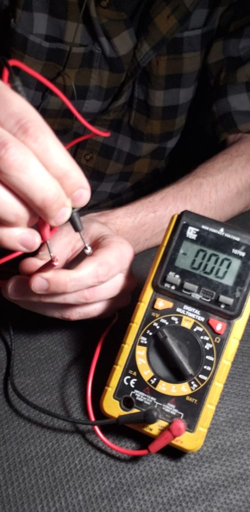
Disconnect Your Solar Array
Before messing with this… It’s important to remember that if the solar panels on the roof are already wired together… there WILL be power coming down and will likely be enough to shock you. I’ve already triple checked checked that my solar panels are disconnected from the wire coming through the roof entry gland and when YOU go to start this part of YOUR project. I highly recommend you do the same.
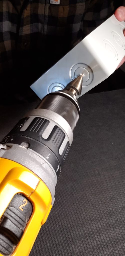
Drill the Holes for the Solar Disconnect Box Wire Glands
Using a step bit and drill, I’m going to drill the holes into the din rail enclosure for the wire entry glands.
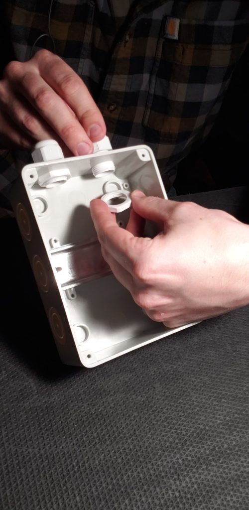
Install the Wire Glands for the Solar Disconnect Box
Since this doesn’t need to be waterproof, it’s fine for wires to share the same wire glands. I’m doing incoming wires in one glad, and outgoing in the other.
If you were going to be installing multiple breakers into this box for, say, a system with multiple charge controller… be sure to offset the wire glands so you can fit two additional ones.
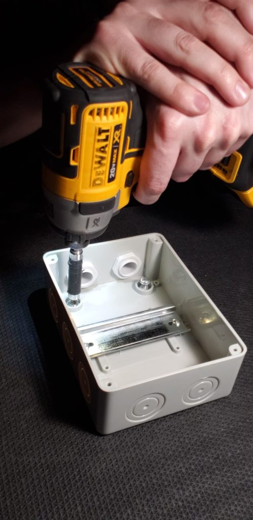
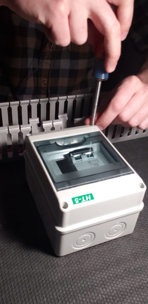
Secure the Solar Disconnect Box to the Backer Board
Using some truss head screws, I’m going to secure the enclosure to the backer board. Four screws should do the trick.
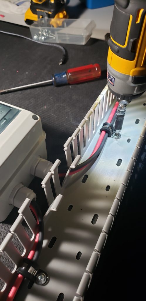
Install your Wire Duct (Optional)
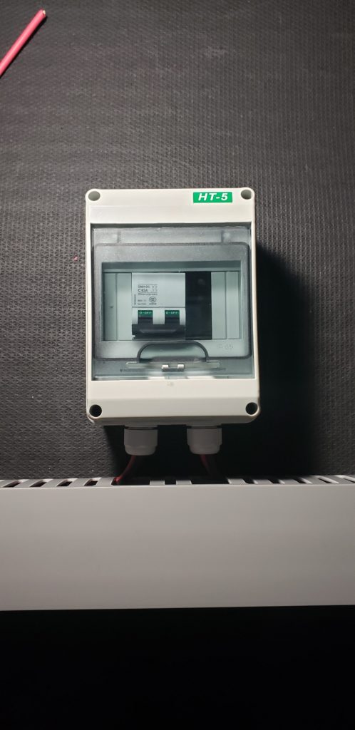
Next, I’m going to install some wire duct. This is completely optional but makes for a super clean install. Wire duct is simply a piece of plastic channel with the little ‘fingers’ on the sides. It’s made to run wires through and the slots make it easy for the wires to ‘exit’ the channel to connect to the components. It has a lid that snaps in place on top and just keeps all of your wires nice, tidy, hidden from view, and adds a nice layer of physical protection to the wire. It simply screws to the backer board with some truss head screws. This is what the final product looks like with the wire duct installed:
Install the Solar Disconnect Breaker into the Solar Disconnect Box
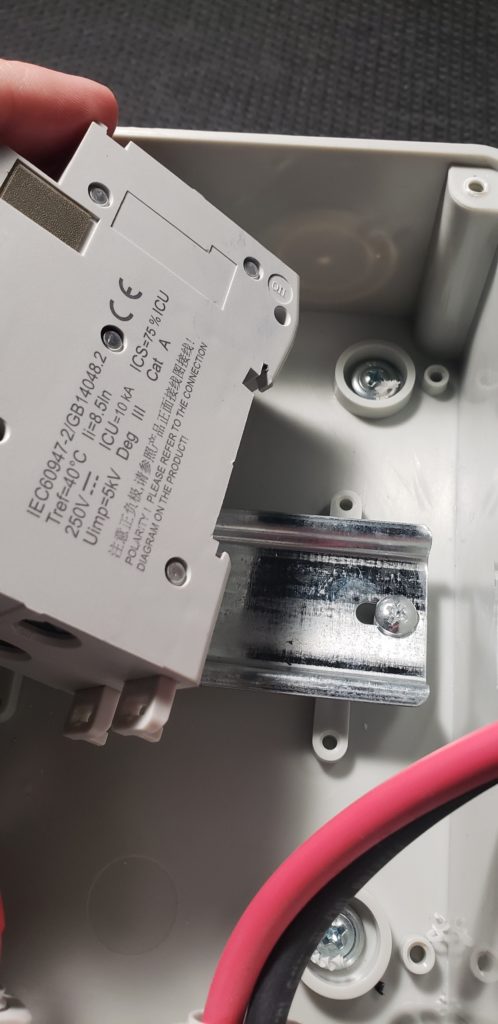
Next, I’m going to install my breaker onto the DIN rail. There is a little lip on the top back of the breaker that hooks over the top of the din rail. On the bottom, there are two little tabs that extend and retract to hold the breaker to the rail… Push the little retainer clips down and clip the breaker onto the din rail.
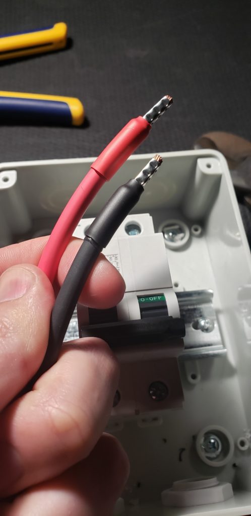
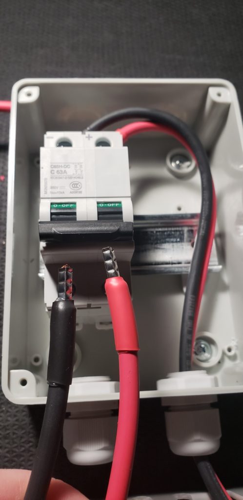
Cut, Strip, & Crimp the wires for the Solar Disconnect Breaker
I’m going to take the wires that are coming from the solar array and measure them out so they can reach the top of the breaker and cut off any excess. Next, I’m going to strip the insulation off of the end of the wire and put a ferrule and heat shrink on the end. I covered ferrule installation in depth in this video and you can check that out for more info: https://www.youtube.com/watch?v=h8CHAVmpPFw
Connect the Incoming Wires to the Solar Disconnect Breaker
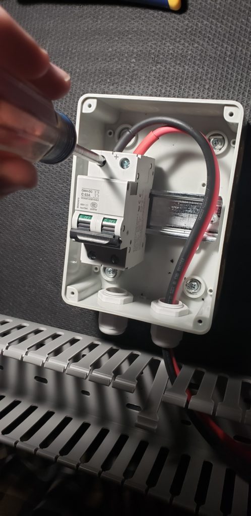
Now I’m going to insert the positive and negative wires into the top of the breaker and tighten down the terminal screws.
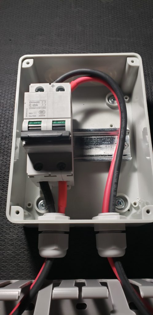
Cut, Strip, and Crimp the Outgoing wires for the Solar Disconnect Breaker
This is the wire that will go from the disconnect breaker to the charge controller. This wire will be the same gauge as the wire on the other side of the disconnect, so I’m going to just use the excess I just trimmed off. I’m going to Cut, strip, and put a ferrule and heat shrink on each one of these wires.
Connect the Outgoing Wires to the Solar Disconnect Breaker
…and then I’ll take each of those wires and put them into their respective spots in the bottom of the breaker.
Tighten the Wire Entry Glands & Reinstall Solar Disconnect Box Cover
Now I’m going to tighten up the wire entry gland…and put the cover onto the enclosure with the provided screws.
Install Cable Clamps to Hold Solar Wire in Place
Next, I’m going to take my cable clamps and put them on the incoming and outgoing wires to secure them a bit more inside of the wire duct. This is a good idea regardless of if you are using wire duct or not.
The next step would be to connect the outgoing wires to the charge controller, but that will be covered in its own blog post and you can read more about that here: https://www.explorist.life/how-to-wire-a-solar-charge-controller-for-a-diy-camper-electrical-system/
Is a Disconnect Between the Solar Array and Charge Controller Necessary?
Short answer: Yes. And here’s why:
NEC 2020 Article 690.13 says that “Means shall be provided to disconnect the PV system from all wiring systems including power systems, energy storage systems, and utilization equipment and its associated premises wiring.
Is a Dual Pole Disconnect Necessary for a DIY Camper Solar Array?
Again, Yes… And here’s why:
NEC 2020 Article 690.13 section (E) States that “ The PV System disconnecting means shall simultaneously disconnect the PV system conductors that are not solidly grounded from all conductors of other wiring systems.
Since camper electrical systems are generally NOT grounded, this means that both the positive and negative conductors from the solar array need to be able to be simultaneously disconnected, and our dual pole breaker does exactly that where those other breakers and switches do not.
What size of Breaker is needed for a DIY Camper Solar Disconnect?
Short Answer. As long as your solar array has a short circuit amperge of less than 50A and a short circuit voltage of less than 250V… You should use a breaker at is at least 50A and at least 250V. Any higher on either of those numbers is fine.
Long Answer: Both the voltage and the amperage of the breaker just needs to be above the voltage and amperage that you EVER anticipate flowing through the breaker.
You don’t want too much voltage flowing through the breaker, as it will damage the breaker. The breaker in the parts list above has a minimum voltage rating of 250V (or 400V, depending which one is in stock). A properly designed camper solar array will never exceed this.
The amperage just needs to be high enough that it will never trip automatically. This breaker is simply being used as a disconnect and can offer NO overcurrent protection in this location.
Providing overcurrent in this location is impossible because the operating current of the array and the short circuit current of the array are nearly identical and therefore impossible to properly provide overcurrent protection for. This is perfectly fine and is well within electrical code/standards.
Again… This breaker is just acting as a switch and is offering no overcurrent protection. This is why I usually use a minimum of 50A/250V breaker even though it is on 10 AWG Wire.
FAQ’s about Camper Solar Disconnects:
Q: Can’t I just use one of the commonly used 12V DC resettable breakers/switches like this?
A: No. You shouldn’t. For two reasons…
1: Those breakers do not satisfy the “Must disconnect both the positive and negative wire” requirement set by NEC 2020 Article 690.13 section (E)
2: Those breakers have a max operating voltage of 48V, 48V, and 24V (respectively, top to bottom) and a properly designed solar array controlled by an MPPT charge controller will VERY MUCH LIKELY exceed 48V.
Installing a Dual Pole Solar Disconnect for your DIY Camper Electrical System – Conclusion
Now you know how to wire a dual pole solar disconnect, how to size your disconnect, and why a disconnect is necessary.
Thanks for reading and I hope you found this blog post helpful and if you did… It’d be awesome if you would share it with somebody, or a group, who you think could use it. Hit the like button, and leave any questions you’ve got in the comments section below. Subscribe if you want to see more DIY camper building tutorials and I… will see you in the next project.

20 Responses
I’m installing a solar system for my father-in-law that will include the factory 100W roof panel and a Renogy 200W ground deploy panel. This will equate to 20V at 15.6amp (parallel wiring) Can I combine the two at the disconnect switch (2 and 2- in and 1 and 1- out)? If i did, my plan was to crimp both into a single Ferrule and likewise with the negative. Running 10AWG wire. I can certainly use MC4 combiners but seems like just another point of failure and resistance doing it that way. I have done 2 other systems but they have all been roof solar systems only in series/parallel so only one set of wires coming into the solar disconnect switch from the roof. Thanks in advance for your help. Your business has helped me install 2 complete systems with 300AH capacity/3000W inverter/800W Solar and they work great!
You’ll want to wire each array to it’s own charge controller. I would strongly advise against combining the roof and ground arrays in this scenario.
Hi Nate, I got the Renogy 400W, 40A MPPT premium kit (before I discovered how in-depth your site was) and it comes with a 40A ANL Fuse to utilize between the panels and the charger. I’ve ordered the components you discussed above and will be following your recommendation.
I’m just wondering if there’s any use to also including the fuse as the breaker is not acting as overcurrent protection?
(Seriously amazing site, btw, that PDF wiring diagram has been a life saver!!!)
I’m not familiar with that particular kit, but here are a bunch of examples/parts/etc on how I recommend setting up the solar charging side of a camper electrical system: https://shop.explorist.life/product-category/all-products/camper-wiring-kits/solar-charging-wiring-kits/
What material(s) are you using for your backer board?
Coin grip flooring makes a great surface to put on a backer board: https://amzn.to/3KQvt1Z For this video; I was using the back of a rug screwed to plywood. I don’t recommend that for anything other than a tabletop demo. 🤣
Since this switch is providing no overload protection, why couldn’t you just use a “Double Pole Single Throw Switch” for both the wires? Thanks!
Mainly because Double Pole Single Throw Switches rated for 250+ VDC don’t really exist that I’m aware of.
Thanks for this post, Nate. For grounded charge sources, would there be any reason / benefit to using a din rail breaker (e.g., if I connected the van starter battery through the same breaker box then to the DC-DC charger), or would a fuse (per your wiring diagrams) be better for wire protection? Could I replace the fuse with a normal single pole breaker to act as a disconnect switch, or would you recommend adding a separate switch in addition to the fuse?
Thanks!
The way I show in my diagrams is indeed the way I recommend wiring this stuff, but feel free to play electrical arts and crafts if you feel so inclined. Just know that I don’t necessarily vouch for any changes.
Hey Nate, thanks for sharing. NEC 2020 Article 690.13 section (E) States that “The PV System disconnecting means shall simultaneously disconnect the PV system conductors that are not solidly grounded from all conductors of other wiring systems.” Does this mean if the campervan ground is tied to the van’s battery and chassis ground, then a single pole disconnect on the positive lead can be used?
The PV negative is NOT connected to the chassis ground, so it is indeed NOT solidly grounded and therefore needs the dual pole disconnect as shown in this tutorial.
Thanks for this. You keep on referring to “NEC 2020 Article 690.13 section (E)”, but it would be great to provide the reasoning for this code. Beware, it’s not just north Americans who use your teachings, but also countries with other electrical codes. Understanding the reasoning, one might see that for very low single panel systems, such an installation isn’t really required… Assuming the mppt carries certain features. Thanks again!
The electrical codes for campers are near non-existant. I use a mixture of NEC code and ABYC standards for my teachings in an attempt to teach people how to build the most efficient, safest systems I possibly can. If somebody feels like they want to follow a different code or no codes at all, that’s their prerogative as I will not be coming around door-to-door and conducting inspections.
Hi Nate
There is a discussion on one of the RV forums I belong to about whether or not the disconnect breaker you reference here is DC rated. One person said if it’s not DC rated and you disconnect under high load, it could melt the contacts. Any thoughts on this?
The good news is I’ve been able to share your website and videos with other folks!
The straight line next to the voltage rating on the breaker represents DC voltage (AC would be a squiggly line). The ‘DC’ part of the “C65H-DC” represents DC voltage. The product page (linked under the parts list) denotes that the breaker is rated for DC voltage no fewer than six times. That said… I’m fairly confident that I’ve shown a DC breaker here. 🙂
Great post, I love your stuff.
Awesome! Glad it helped.
Hi – what wire gland size did you use here? It’s not listed in the materials list. Really, really like your site BTW – thank you! C
The wire glands are included with the DIN rail enclosure.