Ever live in a house that had lights you couldn’t turn off and on by a switch? No? Me either. Let’s keep that streak up. This blog post is going to teach you how to install 12v lights and switches in your DIY Camper
NOW AVAILABLE: 12V Branch Circuit Guidebook https://shop.explorist.life/shop/all-products/solar-wiring-diagrams/12v-branch-circuits/
Quick note before we get started. This is just one part of an overarching “How to Install a DIY Camper Van Electrical System” series. If you’ve just stumbled on this article directly without seeing that, there are likely some things we’ve already covered. If you want to check out that step by step guide, you can do that here: https://www.explorist.life/diy-campervan-solar
Also, we have interactive solar wiring diagrams that are a complete, A to Z solution for teaching you exactly what parts go where, what size wires to use, fuse size recommendations, wire lug sizes, and all kind of other stuff to help save you time and frustration. You can check that out here: https://www.explorist.life/solarwiringdiagrams/
How to Wire 12V Camper Lights to a Battery
Although it is, indeed, possible to wire the lights directly to the positive and negative battery terminals, installing a complete electrical system into a DIY camper is going to involve moving the branch circuits (Lights, fans, USB outlets, etc) away from the battery bank. To do this, I recommend using a power distribution center like the WFCO WF-8950 (https://amzn.to/3kLk6gf). Here is how the WFCO WF-8950 distributes power:
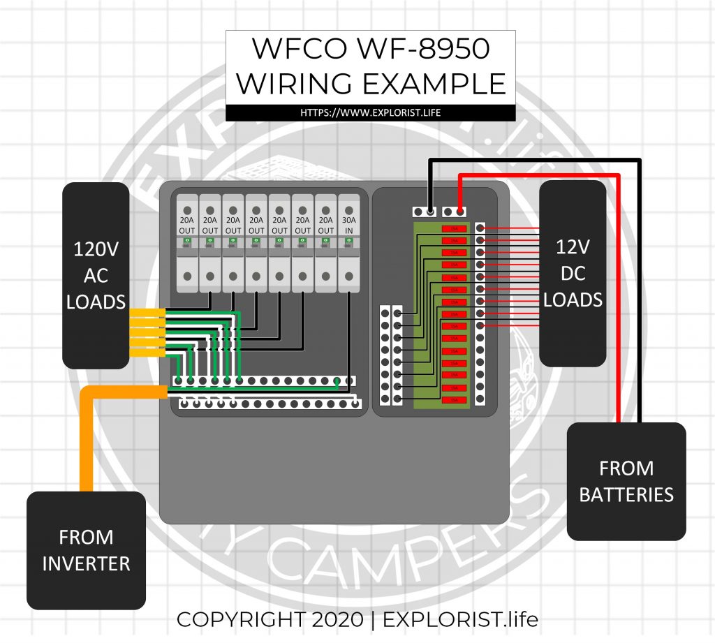
How to Wire a 12V Fuse Block to the Battery Bank
In all of the EXPLORIST.life solar wiring diagrams, I have integrated the WFCO WF-8950 into every one to deliver power to all of the 12V accessory runs. The following diagram highlights the path from which the 12V power distribution panel draws power from the battery bank. 12V power is drawn from the 12V Battery bank and gets distributed through the 12V Busbars (Victron Lynx Distributor, in this diagram) to the major components in the system. From the Lynx Distributor, power goes up the positive and negative wires to the DC side of the power distribution center where there are 15 different circuits ready to send power out through a positive and negative wire to each of the individual 12V branch circuits (lights, fans, usb outlets, etc).
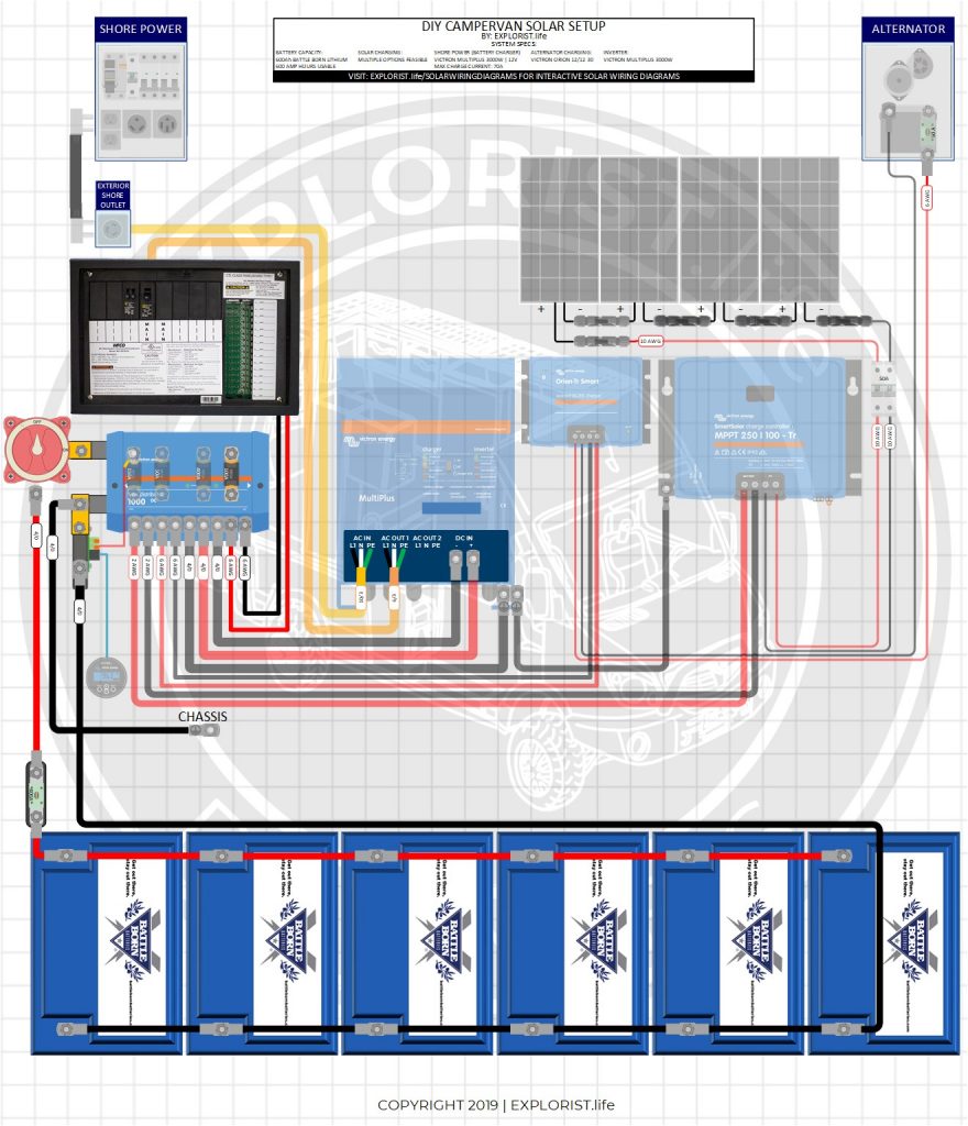
How to Wire a 12V Power Distribution Panel (Video)
This was a very quick overview of how to wire a power distribution panel. If you need a more detailed overview, here is a full length blog post tutorial & video: https://www.explorist.life/how-to-wire-a-power-distribution-panel/

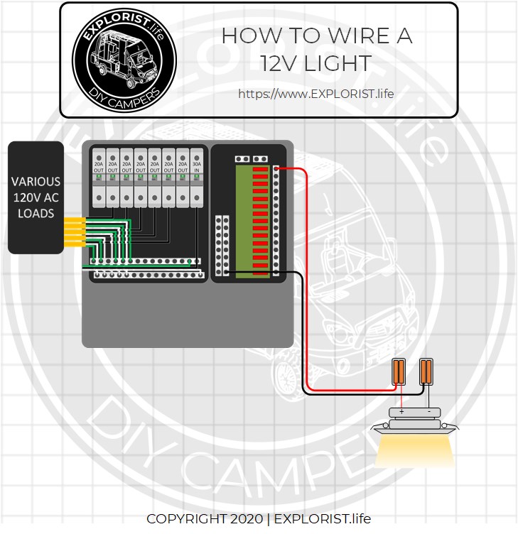
How to Wire a 12V Light
Wiring a 12V light from a 12V battery bank through a 12V fuse block is pretty straightforward. All that is required is to:
- Connect a positive wire to a fused positive terminal in the power distribution panel.
- Connect a negative wire to a terminal on the negative busbar in the power distribution panel.
- Connect the positive wire to the positive wire on the light by means of a lever nut.
- Connect the negative wire to the negative wire on the light by means of a lever nut.
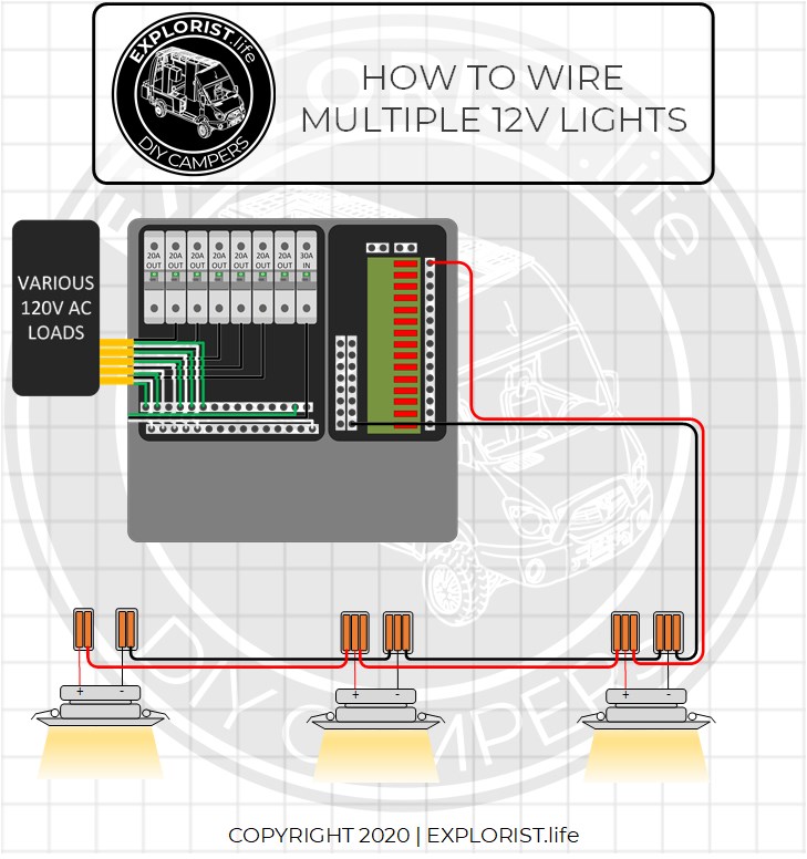
HOW TO WIRE MULTIPLE 12V LIGHTS TOGETHER
The previous diagram may be less than helpful because most people aren’t wiring just a single light. Generally, multiple lights turning on at the same time is desired. Following the same steps as before, but add the following:
- Connect an positive wire to the lever nut connected to the positive wire on the 1st light, and run that to a lever nut connected to the positive wire on the 2nd light.
- Connect a negative wire to the lever nut connected to the negative wire on the 1st light and run that to a lever nut connected to the negative wire on the 2nd light.
- Repeat this process for as many lights as you have.
How to Install 12V Light Switches
Now that you know how power gets sent to a light or multiple lights from the 12V fuse block, it’s time to learn how to wire a switch so you can turn the lights on and off as you wish. This section is going to cover lights that turn on and off from a single location. We will cover 2 way light switches that can control lights from multiple locations later in this post.
12v spst Light Switch Diagram
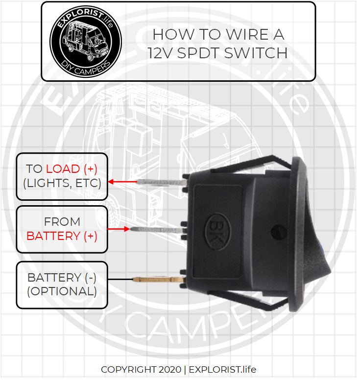
The standard 12V switch we are using to control lights from one location is a “Single Pole Single Throw”, or commonly abbreviated “SPST”. This is the most basic switch. It simply has an on an off position. There are three terminals on the back:
- The middle terminal will accept power from the power distribution panel.
- The top terminal will send power to the lights given the switch is on.
- The bottom terminal is the negative terminal. This simply allows the LED light on the switch to function depending on if the switch is on or off. If you do not wish for the little LED light built into the switch to operate, you can bypass the negative terminal on the back of the switch and not use it.
NOTE: In the rest of the diagrams shown, the Negative switch terminal will NOT be connected. The LED Light on the switch is quite bright and if these switches are located in the same location you are sleeping in, they are very annoying.
How does a 12v light switch work?
The standard 12V switch we are using to control lights from one location is a “Single Pole Single Throw”, or commonly abbreviated “SPST”. The switch simply ‘breaks’ or ‘connects’ the positive wire in the system allowing the power to either flow or not flow depending on if the switch is pushed or not. Here is an example of how the switch works in it’s two positions to control a string of 3 lights:
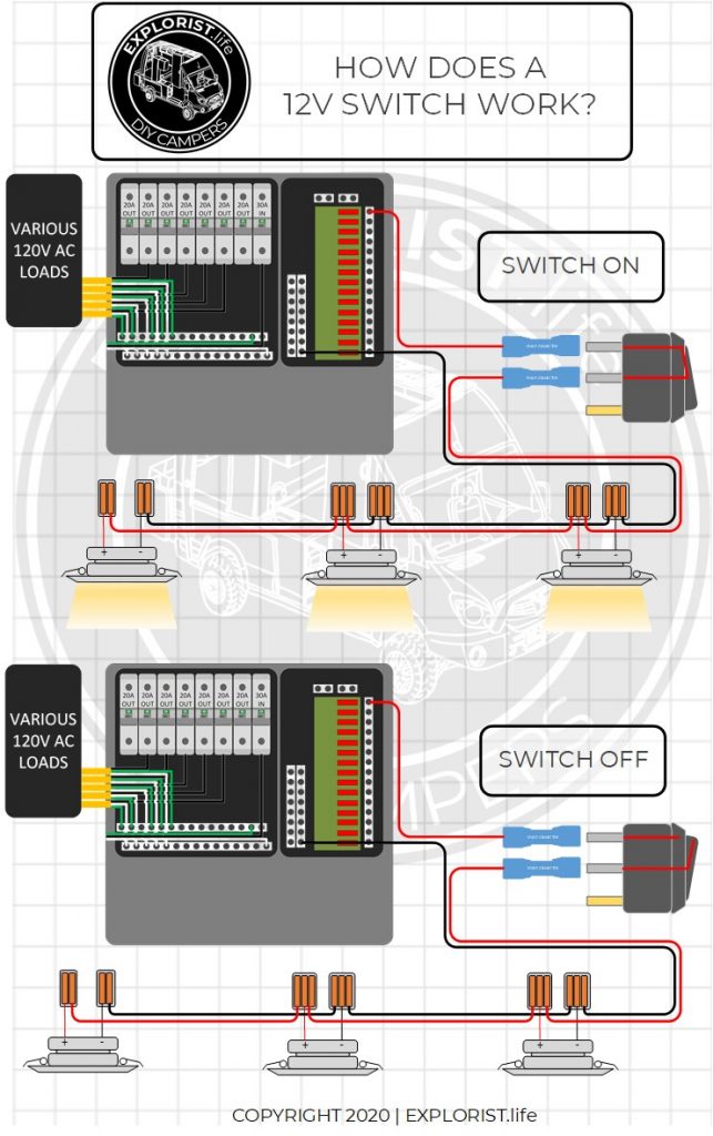
Notice that in this diagram the negative terminal of the switch is NOT connected which means the little led light in the switch will NOT be active.
How to Wire Multiple 12V Lights to a Single Switch
Wiring multiple 12V lights to a 12V switch is just as simple as connecting the positives to positives and negatives to negatives and installing a SPST switch between the fuse box and the string of lights. The switch MUST be between the fuse box and the lights. Here is a 12v lights & switch wiring diagram that shows 12 lights controlled by a single switch:
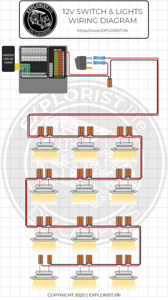
How to Wire Multiple ‘Zones’ of Lights
If you want to have multiple ‘zones’ of light in your camper, you can just ‘copy-paste’ the diagram from above down to the next fuse location in the distribution box. This would allow you to have the switches either in the same locations, or two seperate locations to control the multiple zones. Remember, though, this is showing one switch controlling one zone of lights. Here is how that would look:
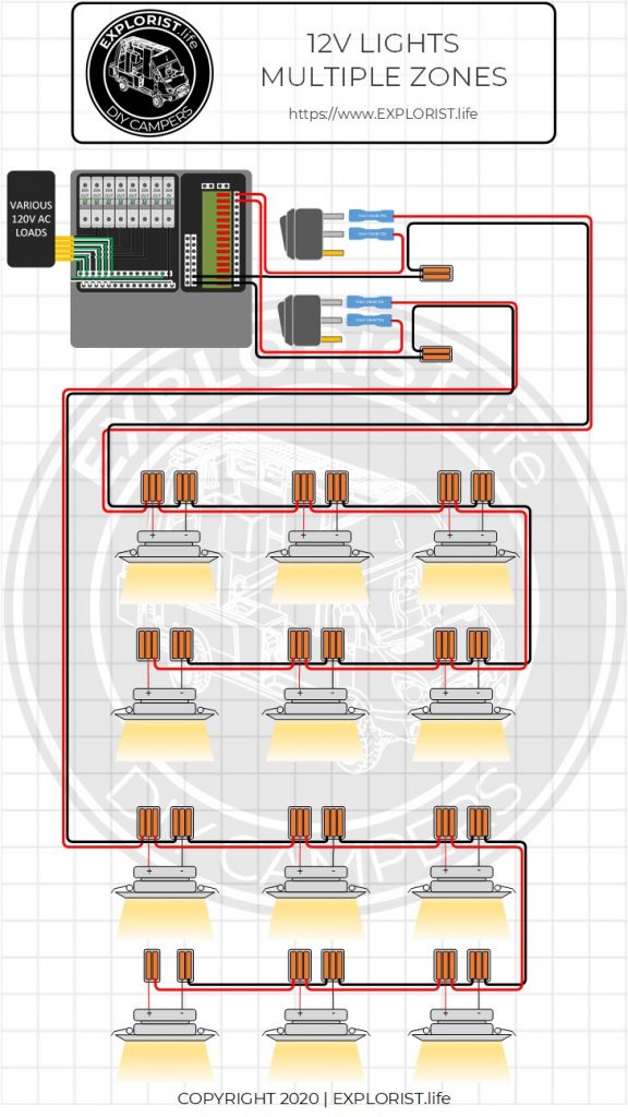
How to wire a 12v 2 way switch
The purpose of a 2 way switch is so that you can have a switch by your entry-way and another by, say, your bed so you can operate the same set of lights from two different locations.
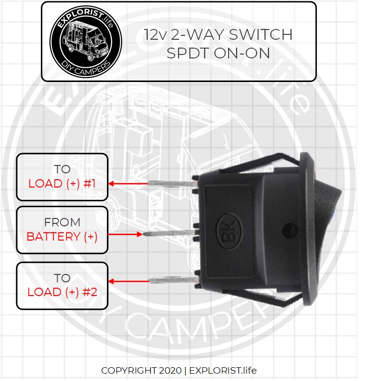
It’s VERY VERY important you get the right switch. The switch you are looking for is a ‘Single Pole Double Throw – On/On’ 12v switch. Here’s how this switch functions:
12V Lights – 2 Way Switch Wiring Diagram
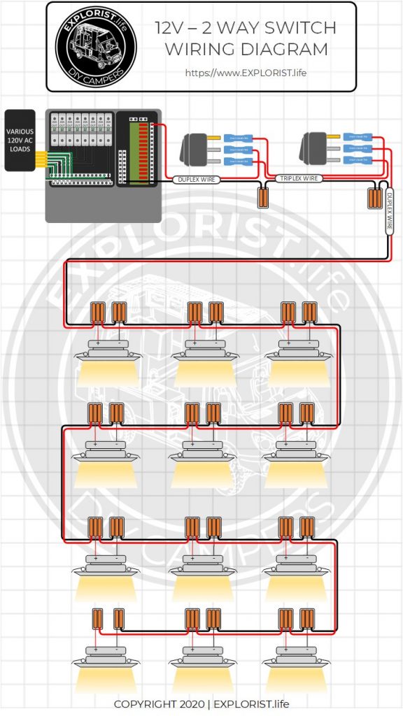
The diagram below shows how to hook 2 way switches together and how to connect them to a string of lights. The positive wire from the 12V Fuse block feeds power to the center terminal on a SPDT On-On switch. The ‘Load 1’ and ‘Load 2’ terminals of the SPDT On-On switch are then connected to the ‘Load 1’ and ‘Load 2’ terminals of the 2nd SPDT On-On switch in the 2nd location. From there, the center terminal sends power to the lights depending on the orientation of the switches.
12V Lights – 2 Way Switch Parts List
Here is a list of parts shown in the above diagram:
| Product | Qty | Link |
|---|
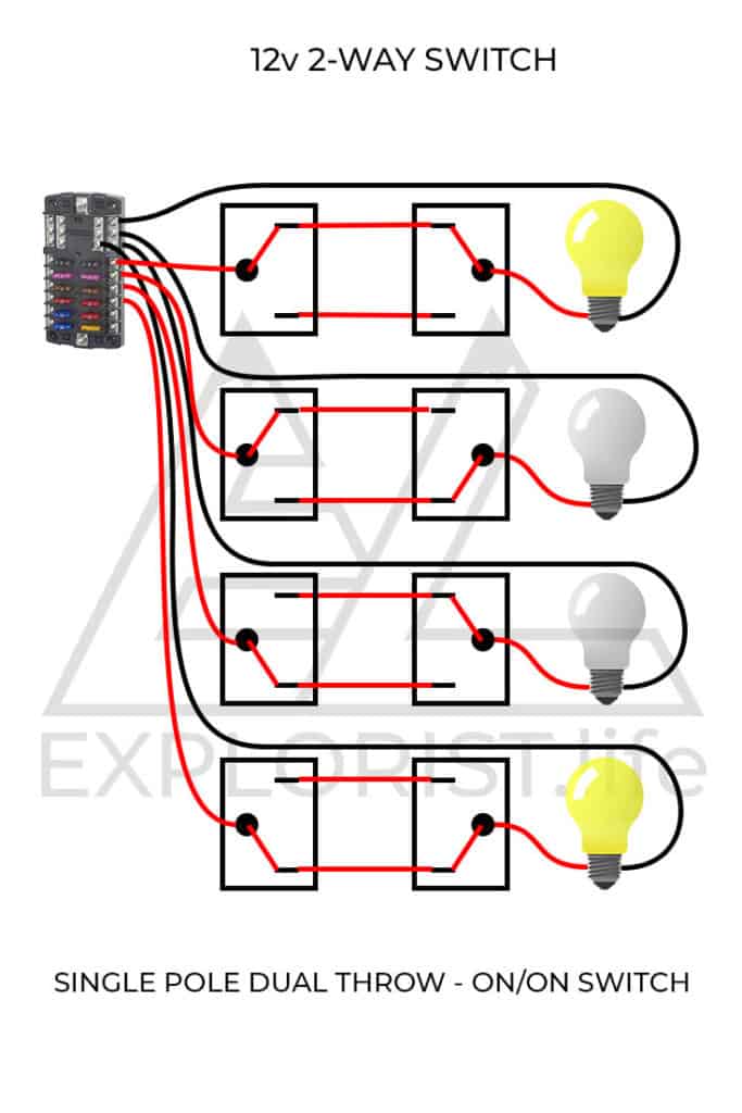
Here is how the switch works in various positions:
Hopefully, you now know how to wire 12v lights and switches into your DIY Camper. If you have any questions, leave them in the comments below and subscribe for future updates.
Now that you know how to wire in a 12v switch and all of your lighting, it’s time for a lesson on how to figure out what size and type of wire to use in your DIY camper van electrical system. Check that out here: https://www.explorist.life/what-wire-to-use-for-diy-camper-solar-system/
Everything that you are learning here is put to use in our FREE Interactive Solar Wiring Diagrams. If you haven’t yet, check them out as they are a complete solution for a camper van electrical system. Check them out here: https://www.explorist.life/solarwiringdiagrams/
Remember, this is just one part of a full camper van electrical educational series. To see all of the individual guides, click here: https://www.explorist.life/diy-campervan-solar
Finally, If you found this guide helpful, It’d truly mean the world to us if you’d share it with somebody who can use it, pin it to pinterest for later reference, or share it to a facebook group when somebody has a question about this subject. Click the bubble in the lower right corner to subscribe to be notified of future updates and as always, leave any questions you’ve got in the comments below.

88 Responses
Hi Nate – Seriously thank you so much for the information provided here. You’re basically ghost-building my electrical system with me.
I have one quick question – when using spade quick connectors, does it matter which side the male/female connector is on? I’ve been trying to google it but I don’t think I have the right terms or something, because I haven’t been able to get a decent answer. I’ve established that female goes where the power is coming from, but what about the negative wires? So if I’m wiring a puck light in, my positive wire from the power source would have the female connector, the positive wire from the light would have the male. Would the negative line be the same? Or would it be reversed because technically the power then is running FROM the light, so the light side would have the female and the power source side would have the male?
I hope that makes sense…
The side that is connecting to the fuse block should be the female end so the exposed ‘male’ doesn’t have voltage on it when disconnected.
Hiya loved your post and diagram wiring very helpful all of it brilliant hats off cheers
Do you know how to wire a 4-way light switch? 3 switches controlling 1 light circuit. Thank you.
At that point… why not just get some kind of remote/bluetooth controlled light? The ability to turn a light on/off from 3 different places in a 20ft long van starts to get pretty cumbersome from a wiring point of view.
hey Nate, see a bunch of questions on running two switches with a dimmer but what if you want the dimmer /switch to be the same instead of running the dimmer before the switch?
for example could this be ran and how would we ?
https://cdn11.bigcommerce.com/s-kwuh809851/images/stencil/608×608/products/2360/20069/RP-1247-Slide-12V-Dimmer-Measurements__89264.1610387778.jpg?c=2
That switch isn’t compatible with two-way-switching; unfortunately.
Hi Nate,
I see your comments below for a dimmer with two switches for my led lights but is there a way to have a dimmer in the three way which also functions as the switch on the one side?
I have never seen a dimmer that would act as you are describing, no.
Hi! When installing a 2 way switch. On your diagram where it says triplex wire, am I using the Green, white and black triplex wire? If so where does the green and white go because the diagram only shows it in red and black. Thank you!
You can use a bit of heat shrink on the ends to denote that it is ‘red’. You’ve got to be a bit creative on this part as triplex wire with a black and 2x reds doesn’t exist.
This has been so helpful. Thank you. I was hoping to have at least 1 dimmer switch in my van. How does this change the wiring, if at all? Can you wire two dimmer switches to the same zone of lights. for instance, dimmer at entrance and at bed for the same lights. That might be a really silly question. I’m about as lay-person as it gets.
Basically, you can’t have 2 dimmers controlling the same zone of lights. If you are trying to make a dimmable light circuit on a 2 way switch, you would wire it as shown in this blog post but insert a dimmer before the first switch. For what it’s worth, this is one of the circuits that is in my 12V branch circuit guidebook: https://shop.explorist.life/shop/all-products/solar-wiring-diagrams/12v-branch-circuits/
Hi there, your diagrams and posts are extremely helpful and I thank you for the info. My question is the 12V puck lights have 22awg wires and I have the 12awg duplex wire from the list but how do you and can you connect the 2 different sizes to run them in series like you describe? Maybe I just missed how it explained or just not quite understanding any help would this would be greatly appreciated.
You should use lever nuts for that: https://amzn.to/38aghN4
Hi
Really struggling with something i thought would be simple
I am looking to add a separate led 12v strip (1m) to an existing 1.5m length led strip and was hoping to do this by adding the positive and negative wires at the connecting wires coming from the switch (it is going to a different area so it is not an extension to the existing strip but i want it to come on at the same time)
When i connect the wires nothing happens – old strip comes on – new one doesn’t. I have connected the new led to a cig lighter connection and it works fine.
Am i missing something in my logic?
That is definitely how that SHOULD work.
@Nate Yarbrough, anything else that could be wrong ?
Not immediately. I would recommend using your multimeter to poke around and see if you are actually getting voltage to the locations in the circuit that you should be getting voltage.
@Nate Yarbrough, ok will try that – thanks
SO helpful, thankyou! Do you have diagrams for people who arent installing solar? Its not intuitive for me which wires and which equipment to eliminate. I’ve read every one of your posts several times, and even created a spread sheet of definitions and step by step procedures, but often youre explaining something basic (like wiring a light switch) in the context of solar and I just dont know how to make sense of it!
I don’t have any diagrams that don’t have solar BUT… all of my diagrams, the solar charging leg can simply be omitted by ignoring EVERYTHING between the Lynx Distributor and the solar panels: https://www.explorist.life/solarwiringdiagrams
Thanks for sharing! I’m no electrician but I’m following along and feeling confident so far. I’d like to add a dimmer as well – how much complexity would that add? I’d like to be able to turn all ceiling lights on/off from the back and front of the van using the solution you show here, but also add a dimmer for occasional adjustment. It may not be most efficient use of wiring, but I think I can make it happen by having the two 2 way switches and the dimmer in series before branching off the actual lights.
Your proposed solution of adding the dimmer before either of the switches is the direction I would recommend going with that. You wouldn’t be able to dim the lights from both ends, but that is just going to be a system limitation.
Just the diagram i’ve been searching for! – Super simple!
Great! 🙂 🙂
Fantastic site, thanks for everything! When wiring 110v AC all connections and switches etc must have a junction box. I can’t find anywhere that suggests this is required for 12v. How do you protect the connections for 12v at switches and fixtures? This is a trailer rebuild project. Thanks in advance, Eric
A junction box for 12v devices is indeed not required. For making those wire connections, I recommend ‘Lever Nuts’: https://amzn.to/3mwq8S1
Nate,
Can you share a diagram around how one would use a terminal block to wire multiple zones of 12V lights together so that it only takes up one at most two DC panel circuits?
For example: 12V, 3W (QTY 16)
Zone 1 – Entry Way Puck Lights (QTY 4)
Zone 2 – Bed Area Puck Lights (QTY 4)
Zone 3- Headliner Puck Lights (QTY 2)
Zone 4- Drivers Side Under Cabinet Puck Lights (QTY 3)
Zone 5- Passenger Side Under Cabinet Puck Lights (QTY 3)
I actually just released a guidebook that will show you how to wire a switchpanel (with a wire/fuse size cheatsheet) that will show you how to do just that: https://shop.explorist.life/shop/all-products/solar-wiring-diagrams/12v-branch-circuits/
I’m trying to install a 12v panel in my RV that houses a a cigarette lighter socket for my CPAP machine. The easiest and best install location would be right on the wall in front of the bed, right next to two switches – one for the ceiling lights above the bed and one that retracts and extends the slide out. I have easy access to the wires for each switch, and I’ve identified the + and – wires for both switches. Here’s my question – if I take power off EITHER of those switches, won’t operating the new panel close that switch’s circuit and operate the original switch’s load, just as if I had thrown that switch? In other words, wouldn’t operating the CPAP turn on the lights or operate the slide, as well, depending upon which switch I hooked into?
I must recommend running a dedicated circuit for that purpose unless you know, without a shadow of a doubt, that the lighting circuit wire is big enough for your cpap (I would guess it is not). Running a dedicated wire is the ‘correct’ way to accomplish this. Do it right; do it once.
Perfect!
Any thoughts on being able to use color changing recessed lights like these? https://www.amazon.com/gp/product/B07WBYZGG6/ref=crt_ewc_title_srh_2?ie=UTF8&smid=A1IUK570D3YJXB&th=1
My concern is I believe they are designed for AC so dont think they can be used without the inverter. Any good recommendations for color changing lights?
Those lights are, indeed, 120v and would need to be powered through the Inverter. Although I have not personally used these, it does appear that the following are 12v lights and would be worth investigating/testing: https://amzn.to/3irJmXi
Hi,
Currently in the pre wall phase where I want to run all of my wires before I install any walls and my concern is running out of DC fuse spots. For example I will have 2 Maxxair fans and then a natures head vent fan and I am wanting to connect them all in parallel to avoid wasting 2 extra fuse spots. But my concerns are creating too long of a wire and one item blowing the fuse for everything and then none of the fans work. If I did connect multiple 12v items but kept the Amps below 15 (using 12G that you recommend) would that work or is it better to add an additional 12v fuse box? Very quickly eating up my fuse spots with – 2X Maxxair Fans – Main Area lights (Dual Switch) – Heater Control Panel – Toilet/Shower Vent – Bed lights (Dual Switch) – WeBoost – 12V Master Panel by Bed – Garage Lights – Roof flood lights – Fridge – Freezer – Gray Water Solenoid – Zero Breeze AC (Any thoughts on this?) – and i keep thinking of more/extra lines I want to run just in case.
Planning on working and living full time so will have 600AH of batteries and 900W solar.
You can definitely wire multiple devices on one circuit; just be sure to add all of the amperages of all the devices on the circuit together when you are figuring your wire size calculations.
hi, im studying your drawings of light circuits but struggling to understand what the orange blocks are just before the puck light.
thanks
Those are lever nuts. 🙂 https://amzn.to/3h6LVMI
Thanks for taking the time to make wiring diagrams. Well done!
Hi this site is just amazing so thank you. So my question is I am linking led lights as per you diagram. Rather than run the neutral back to the fuse can I connect it to the switch neutral? Secondly what do you recommend to join the leds? The ones I have each come with a length of cable and are pre wired? Thanks
The negative wire needs to connect all the way back to the fuse block.
For connecting the leds together, lever nuts are nice for this: https://amzn.to/2YXkNbY
Thanks for sharing the information and insights! I am hoping to wire two SPDT to six LED lights. Can a dimmer be wired “ahead” of the first switch? Thanks again!
Yes, the dimmer needs to be wired before any of the switches.
Hi. The ground of the spst switch is only to allow the LED to light up when switched on? If have multiple SPST switches for different accessories, can the ground of each switch be linked together to save me having to run many individual ground cables?
Cheers
That should be fine.
I want to use the same DC branch from the DC distribution panel to have two separate lights and switches on it. Would I run the postive wire from the panel with 2 wire connectors to create a separate line to each switch then light? Then have a negative wire run back to the panel that each light would connect to for ground?
With something like this: https://www.amazon.com/Nilight-Terminals-Self-stripping-Insulated-Disconnects/dp/B07CP987BN/ref=sr_1_4?dchild=1&keywords=wire+splice+connector&qid=1587437353&sr=8-4
Or is there a better way?
Super sorry, but I’m not sure I’m following what your plan is. You could always do a bench test with your proposed configuration to see if it would work. Also, I don’t like those splices. They have a tendency to make wire very weak. I like these much better: https://amzn.to/3eEt6kc
I was worried about that as I sent it. I don’t need a single line running from my dc fuse block/distribution panel for each individual light set with switch, right? I have 12 slots on my fuse block/distribution panel, but 14 different 12v things (sets of lights, outlets, weboost, water pump, etc). How do I double things up on one slot in the fuse block? You showed how to chain outlets on the wiring accessories page, but I want to stay away from chaining outlets due to higher amperage. I figure my led lights are very low amperage and could double up on a slot on the fuse block. How would I do that?
I’m wondering the exact same thing. Is the answer to use a terminal block to wire all the lights together before sending them to the fuse panel? That or could you just use these splice connectors to connect them all?
You can just use splices for that. Lever nuts are a good choice for that: https://amzn.to/2YXkNbY
Hello I’ve wired up led lights in my van with a switch at the side door and switch at the back door on the 2 way switch but wanted to know how and if I can include another switch to the drivers side so I can control the lights from all 3 points independently thankyou
Maaaaybe… I haven’t tested that but briefly thinking about it, It may work…
thanks man!
No problem! Happy to help!
Thanks for the write up! If you are wiring up the switches in two-way style, are you able to get the LEDs on the rocker to light up? I know you mentioned you don’t prefer for those LEDs to come on, just wondering if it was possible 🙂
Single Pole Double Throw On-On switches generally won’t have an LED light.
What if you wanted 3 switches instead of 2? I want one by the back door, the side doors, and one on the cab….
In that case you should look at some kind of remotely activated switching relay, probably controlled by some kind of Arduino unit. (it’s going to get quite a bit more complicated if you need 3 switches)
Nate I have been following this for a while and am now getting to my wiring. I want to install the SPDT on/on you describe above. This is a horse trailer conversion and most original lights are grounded to the frame at the light instead of running ground all the way back to the fuse box. Is this a wise thing to do? Will this work in this application?
I’m a big fan of running a dedicated ground wire.
Hey, is there a way to make the led light in the switch light up when the lighting is off so I can see the light switchin the dark? Thanks
I don’t believe so.
Nate,
Thanks so much for posting this, so helpful! I’m having trouble locating a spdt on-on round switch. Amazon lists on/off or on/off/on. Where did you find yours?
I can’t find them on Amazon any longer either. Here’s another link: https://www.delcity.net/store/Non-Illuminated-Round-Rockers/p_788796.h_788835.r_IF1003?mkwid=svoLfuaq8&crid=38094426869&mp_kw=&mp_mt=&gclid=CjwKCAjw29vsBRAuEiwA9s-0B7blRdZeF-5CWmbTmhDFglWxXcA79bIPJ8WGAKrixwC2zwvLN1r15xoCc1MQAvD_BwE
Ahhh, this is so helpful! Going to be referring back to this when I get to the light installation. Thanks a heap! A great informative read.
Cheers! 🙂
Ryan
Thanks for the info! Would it be possible to wire a spdt switch and a dimmer switch to the same set of lights? If so, would it be wired the same as your diagram with 2 spdt switches? Here’s the dimmer I am referring to: https://www.amazon.com/dp/B079TJTP1W/ref=cm_sw_r_cp_api_i_
Thanks,
Eric
It would be similar. You’d want to add the dimmer switch to the wire that’s receiving power from the battery. It’s tough for me to speculate, though, what would happen if both of the switches were dimmer switches.
Great information. I was replacing a 12 volt light switch and noticed the previous owner had an additional brown ground wire coming off their switch but it didn’t appear attached to anything. The house 12V battery is grounded on the (-) wire (in this case a white wire) to the frame. The white wire goes from the switch (no led to avoid) back to the converter and battery (-) which is grounded. The hot or (+) wire is black and leads into the switch as well. So the additional brown wire seems redundant, so I’m assuming the brown wire was carry over before the battery was grounded or they added but didn’t need it. Does this sound right to you? And in your diagram it doesn’t say but the lack of an additional ground wire makes me believe you’re (-) is grounded on the (-) battery side?
Tough to say for 100% sure without actually getting hands on the issue. Seems weird for sure.
Hi Nate,
Thank you for all this goldmine… I’ve been on it for the past couple weeks, many hours a day haha.
I can’t figure out if I should wire the leds in series or parallel.. You show parallel but everywhere else I look I see people saying series is the way to go. I’m a bit lost here I must say… From what I understand parallel delivers the same power to each when series divides it.. So assuming power supply comes from the 12v box I should use parallel for the leds to work properly ? then size fuse and wire accordingly, and if I’m to wire in parallel, use these 3 way conductor connectors to link them ?
Hope it makes sense,
Much love all the way from France!
Glad it’s been helpful! If the lights are 12v lights and you are powering them from a 12v source, they MUST be wired in parallel, else they won’t work.
If the lights are anything other than 12v lights, 3v lights for example, you’d have to wire 4 lights in series for them to get to 12v; then you could wire sets of 4 lights in parallel.
Long story short: just get 12v lights and wire them in parallel.
When wiring multiple lights, you show a butt splice crimp connector with one (+ or -) wire of the light going into one end and two wires going into the other end. Are you just crimping both of those ends together into the butt splice connector?
Try these instead: https://amzn.to/2FmkiiO
How would you go about connecting three wires with those connectors?
You should try some Lever Nuts: https://amzn.to/2YZNYw9
Great work on the info provided.
I see you have wired the LED lights in parallel and am wondering if there are any issues if you were to wire in series creating a “loop” with the wire vs. what you show?
Wiring them in parallel keeps the voltage correct. Wiring those particular lights in series will not work.
Great info, thanks! Question Ford Transit 250 with standard LED interior lights. I interrupted the ground from each light to the switch you show, then grounded the switch seems to work fine. But after awhile it just shuts off. I know everything is on a loop, just want to make sure I am not damaging anything in the electrical system?
No problem! Unfortunately, I dont know about your problem/system to accurately diagnose your issue. I can try again if you give me more info.
Hello Bill,
If I understood correctly, you have added a switch to the existing OEM interior light circuit and you haven’t disconnected it from the interior light power supply circuit.
If this is the case you will need to isolate the circuit and provide a new power source with a fuse to prevent the the courtesy time delay of the interior light circuit. The only thing to note is that you will loose the ability to have the interior lights come on when you open the doors.
Hi
I have a transit van for work and most of the time I have back doors open and the tear interior lights start on for 30 mins then go off but come on again if I open another door
How would I fit a switch or switches to the lights so I can turn them off during the day
I have 12v 5050 led strip lights fitted
Thanks
You’d be looking for the cargo light circuit under the dash and installing an in-line switch there you could turn off during the day. I’m not sure where exactly you’d find that circuit but looking in the fuse box would be a good start.
Hey Guys, these instructions are so great, Thank You!
So here’s my question, for your Exterior LED Light Bar and Pods; Are those ran though the Chassis battery with a harness and relay, or though the house fuse box? Ideally I would like to have the front Light Bar with a dash switch, but my perimeter lights on switches in the back. What would be the best way to approach this?
Thanks and keep up the great work, the updated site looks awesome.
Ours are powered off of the house batteries. I haven’t covered relays and such on the site yet (2/26/19), but will get to it eventually. We have all of our lights on switches under the dash. The switches activate a relay in the back that turns on the lights outside.
If I were doing it over again. I’d have a switch mounted up front that turns my light bar on only when my high beams are on. I’d also have a 2 way switch for each ‘zone’ of the peremeter lights, one switch under the dash, one switch in the back somewhere. Those would all activate relays that would turn the lights on.
I haven’t purchased any solar equipment yet, so the numbers needed in your worksheet is null.
My plan is to use renogy mono panels, 3-160W, all i have room for.
The only items that will run 24 hours is an IceCo VL45 fridge/freezer.
Most of my appliances are 120V which i have planned on putting (5…3 standard outlets and 2 GFCI)all 120V outlet, of course not use all the time..
I’m not planning on any light switches, using “hand waved” puck lights via an adapter with plugs in with an adapter.
What I need is: if correct…
Size of mppt…100/40
Pine SINE Inverter…
…GoWISE Power PS1005
1500w-cont/3000W Peak.
Blue Sea Safety Switch…
…Type?
Busbar type?
Fuse Box type?
Etc…..
I’ve purchased 12 gauge wire to wire 120V outlets, 3 on one side, so ponytail connections.
2 outlets on other side, ponytailed as well. All wired back to fuse box.
I plan on having Shore Power, have purchase wire 10 gauge (30amp).
I have made a list of all my electrical (wants) laptop, printer, fridge/frz, coffee maker, etc. Most will be plugged in when use/unplugged when done.
I would like to install an Isolator too, but solar first for I have only 3 months, then i wont have a place to so any building.
I tried “jimindenver”, but he never responded. He was going to charge $500, but he’s never responded.
3 months isnt alot of time
Robert
rp7313226@gmail.com
Sounds like a cool project! I’m not really sure what you are asking though… If you are looking for component recommendations, I have wiring diagrams and parts lists available here: https://www.explorist.life/solarwiringdiagrams None of them have 1500w Inverters, but this should get you going in the right direction.
Could you tell me what program you use to make those diagrams?
I use Microsoft Visio for all of my diagrams.