
One of the first electrical projects you should tackle in your DIY Camper van build is installing the 30A shore power inlet. Since the 30A shore power inlet needs to be installed in the side of the van (traditionally), it’s best to do that before the walls go up and before you start insulating.
This blog post will walk you through installing a 30A shore power inlet into the side of a DIY camper van and connecting the 10 AWG Triplex wire to the inlet. We will not be connecting the other end of the wire to anything in this tutorial as that will be covered in an upcoming ‘How to Wire a Victron Multiplus Inverter/Charger’ blog post.
Video Tutorial – Installing a 30A Shore Power Inlet
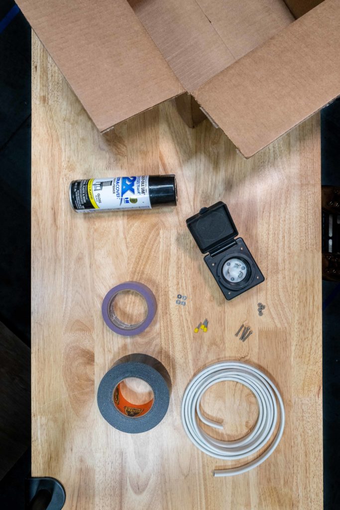
Parts Needed
Here is a list of parts we need for this project:
- EXPLORIST.life 30A Shore Power Inlet Wiring Kit, which includes:
- You’ll also need:
Tools Needed
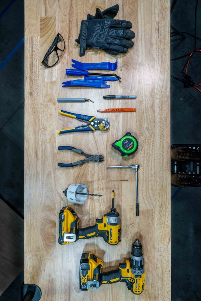
Here is a list of tools we need for this project:
- Cordless Drill
- ⅛ in. Drill Bit
- 2 7/8 in. Hole Saw
- Screwdriver or Impact Driver with a Phillips Bit
- 11/32 in. Socket and Ratchet
- Diagonal Cutters
- Self Adjusting Wire Strippers
- Sharpie
- Mechanical Pencil
- Deburring Tool
- Trim Removal Tools
- Tape Measure or Ruler
- Work Gloves
- Safety Glasses
- Shop Vac
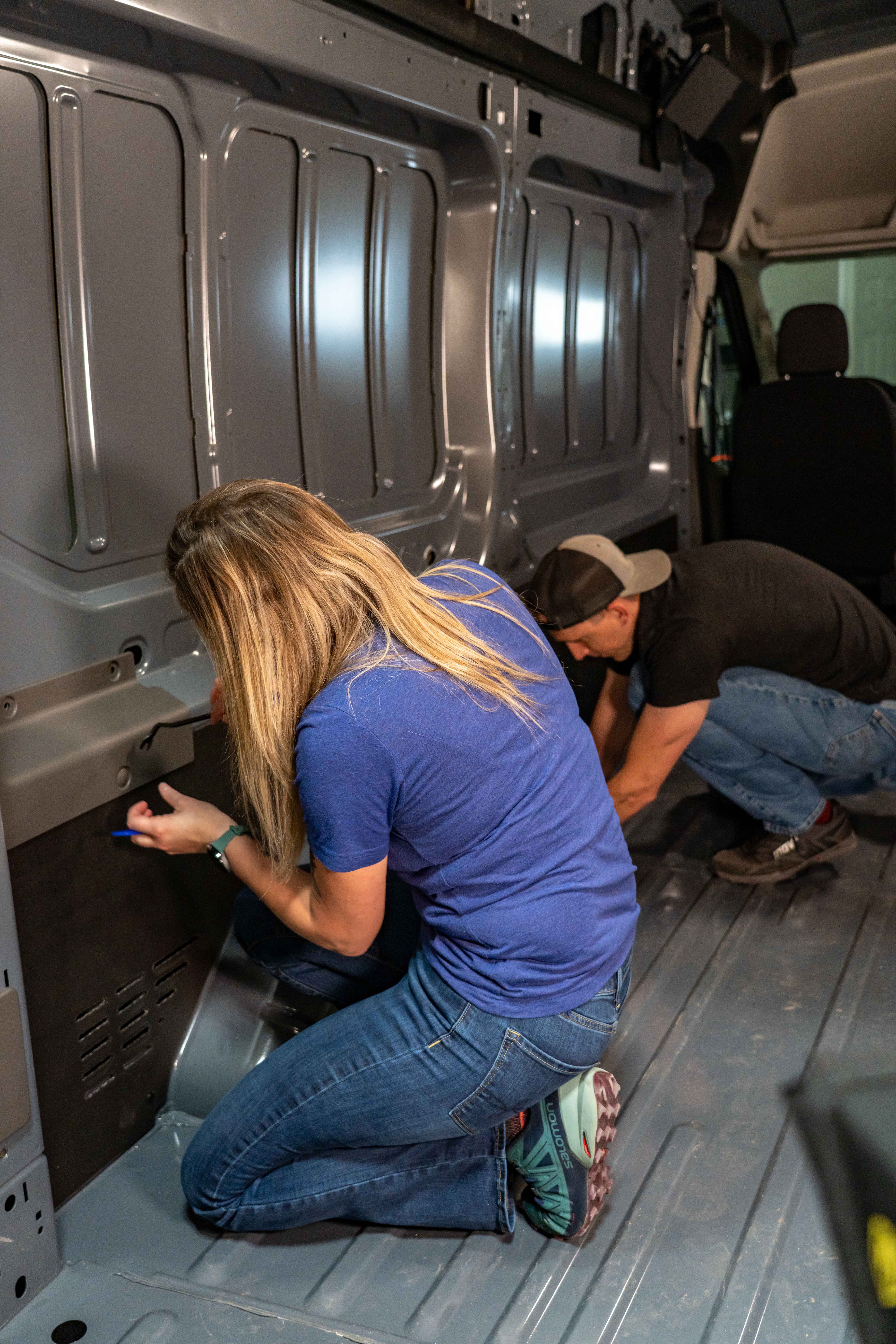
Choose Shore Power Location
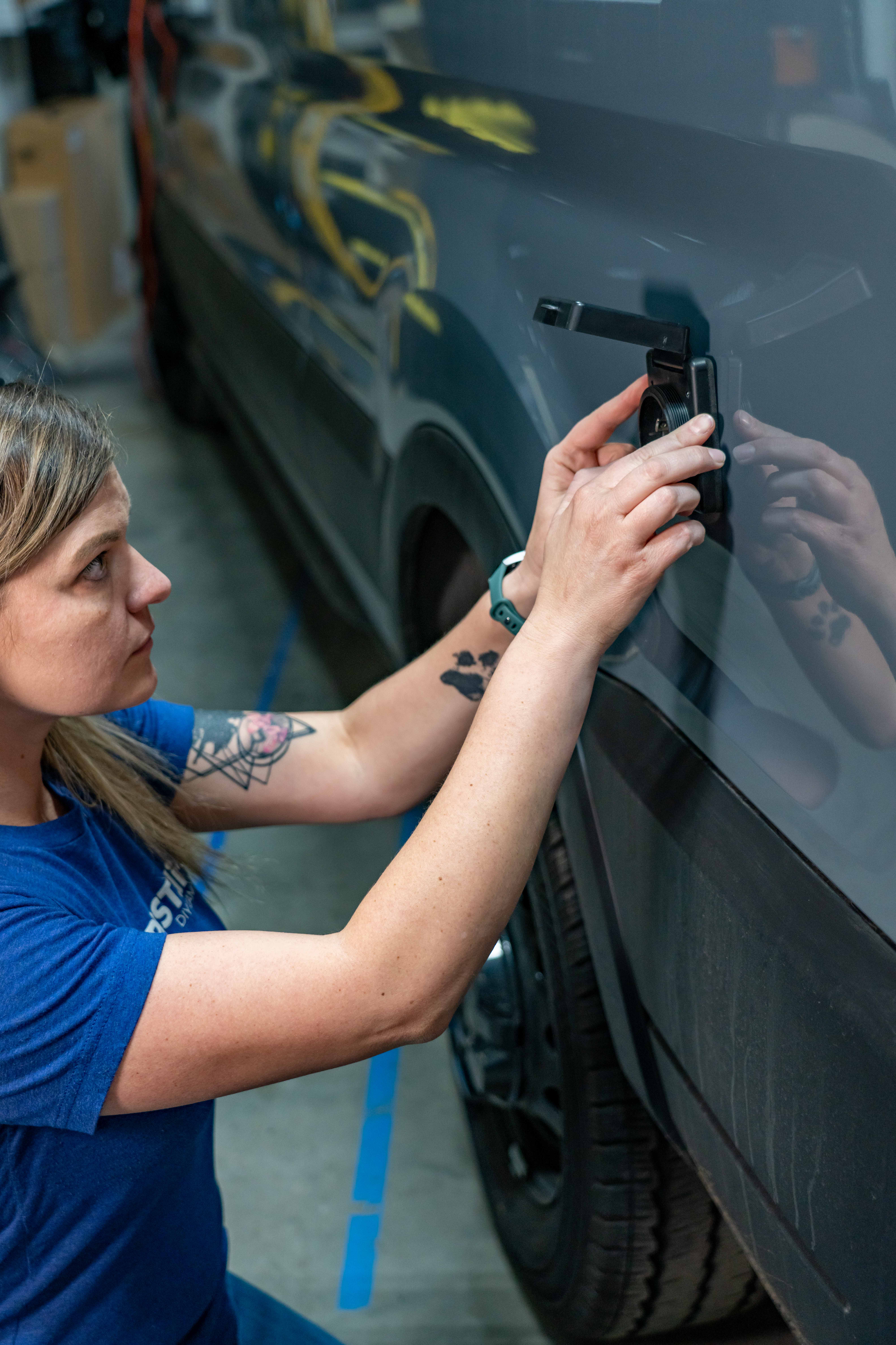
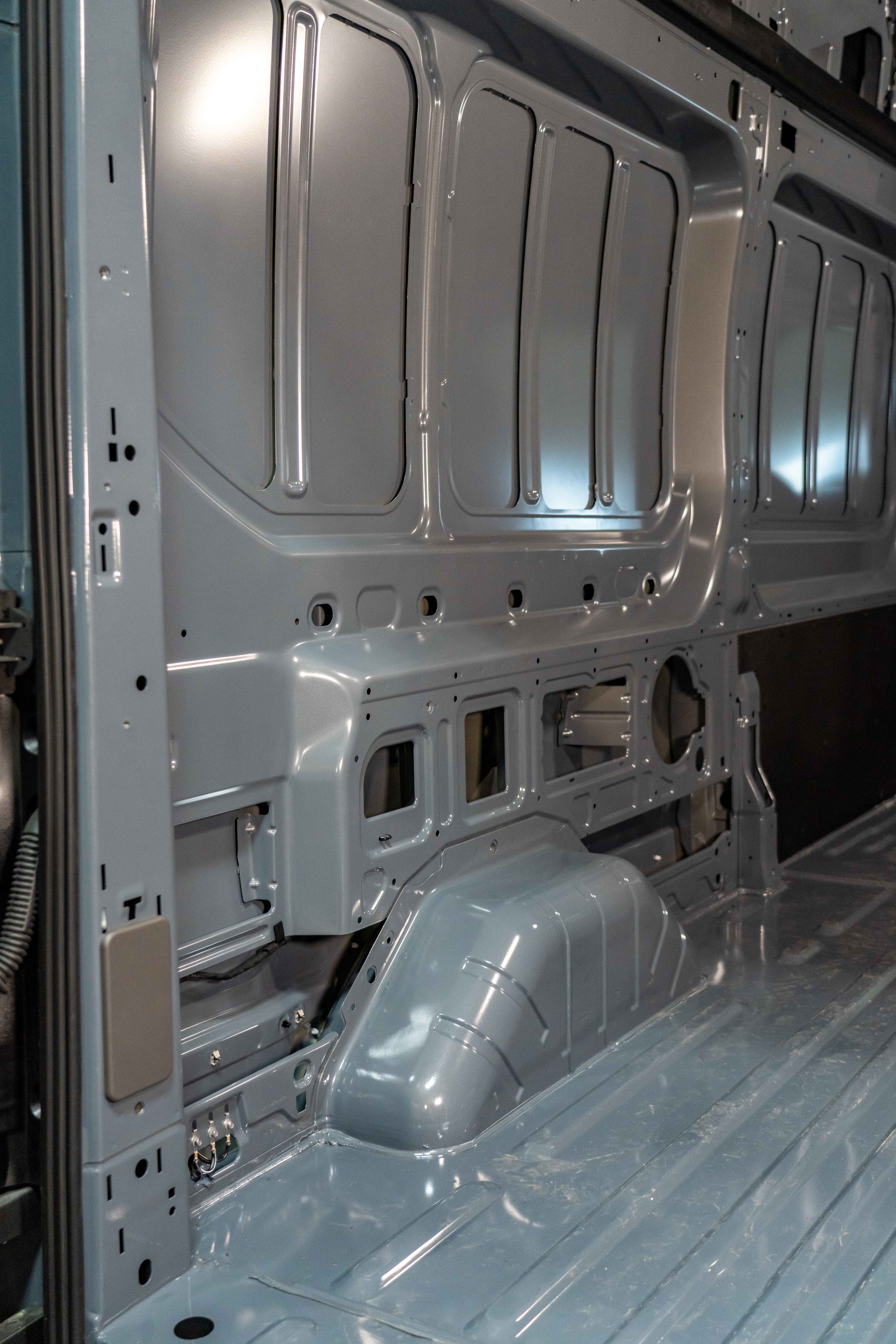
We are going to install the Battle Born Battery bank and other related power equipment over the drivers side wheel well of this van, so we will be installing the shore power inlet on the other side of this wall back here on the rear quarter panel.
Remove Inner body panel
We needed to gain access to the inside of the rear quarter panel so we removed the factory installed panel by using a trim clip removal tool and working our way around the panel removing the trim clips so we could get the panel out of the way.
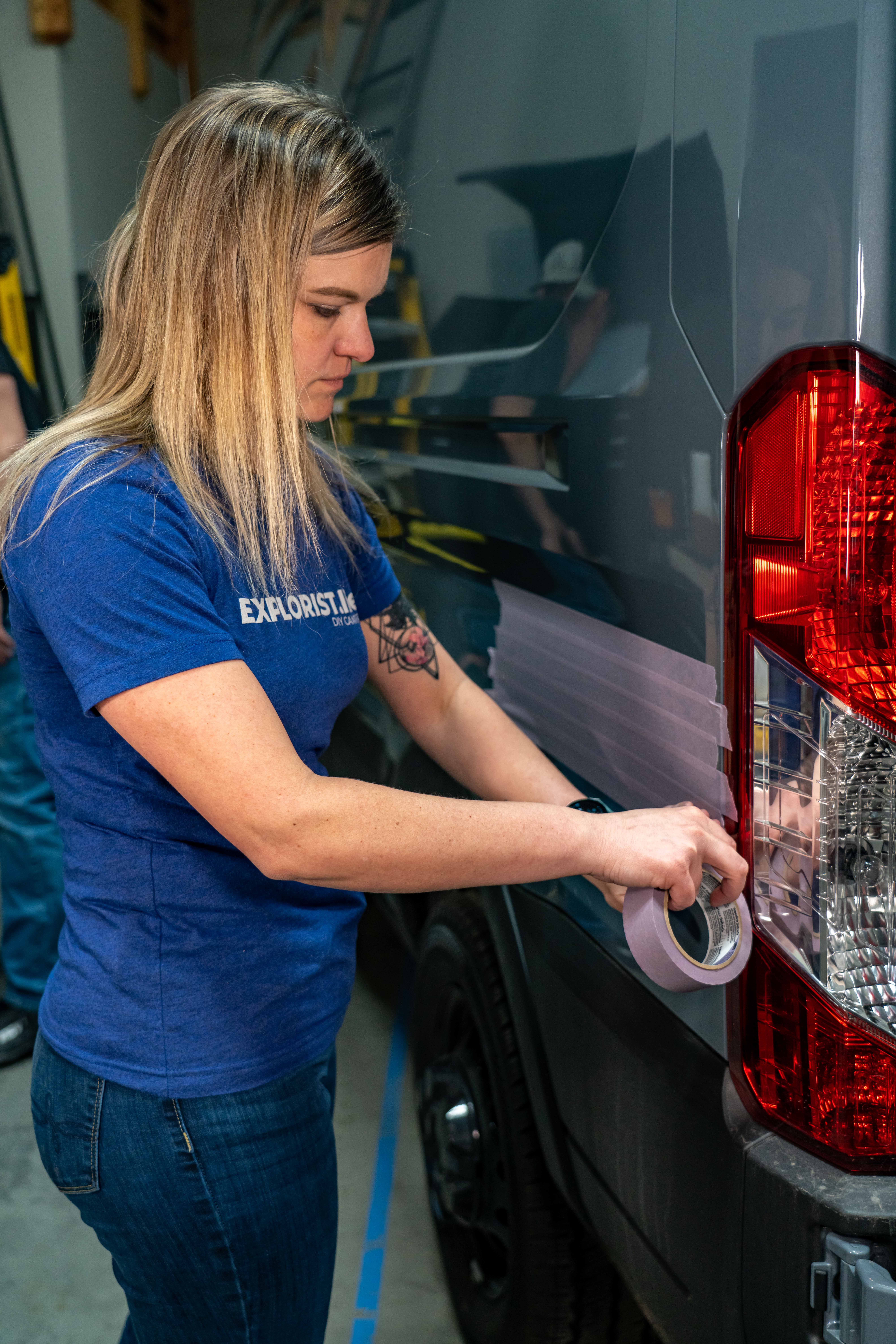
Protect Shore Power Location w/ Painters Tape
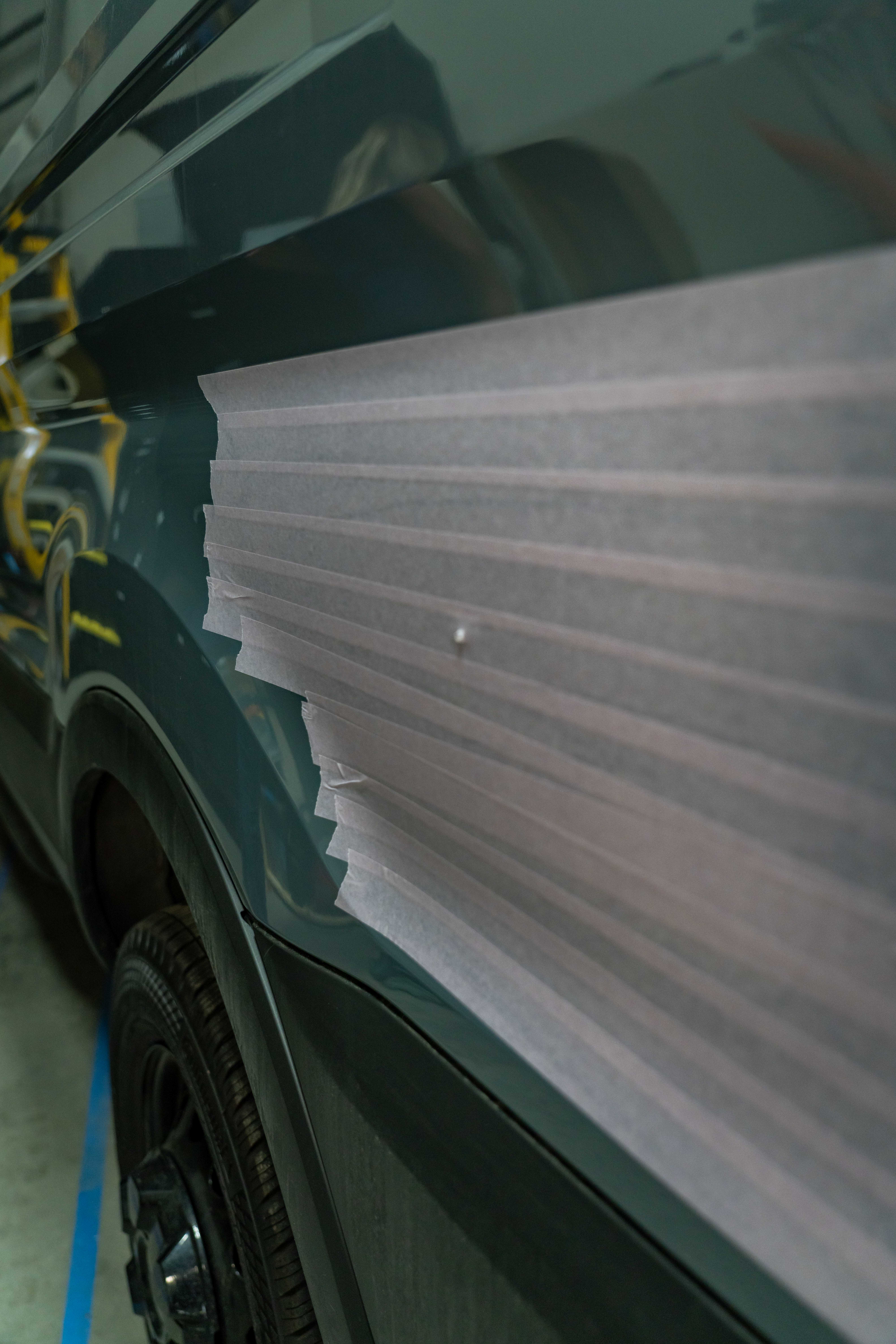
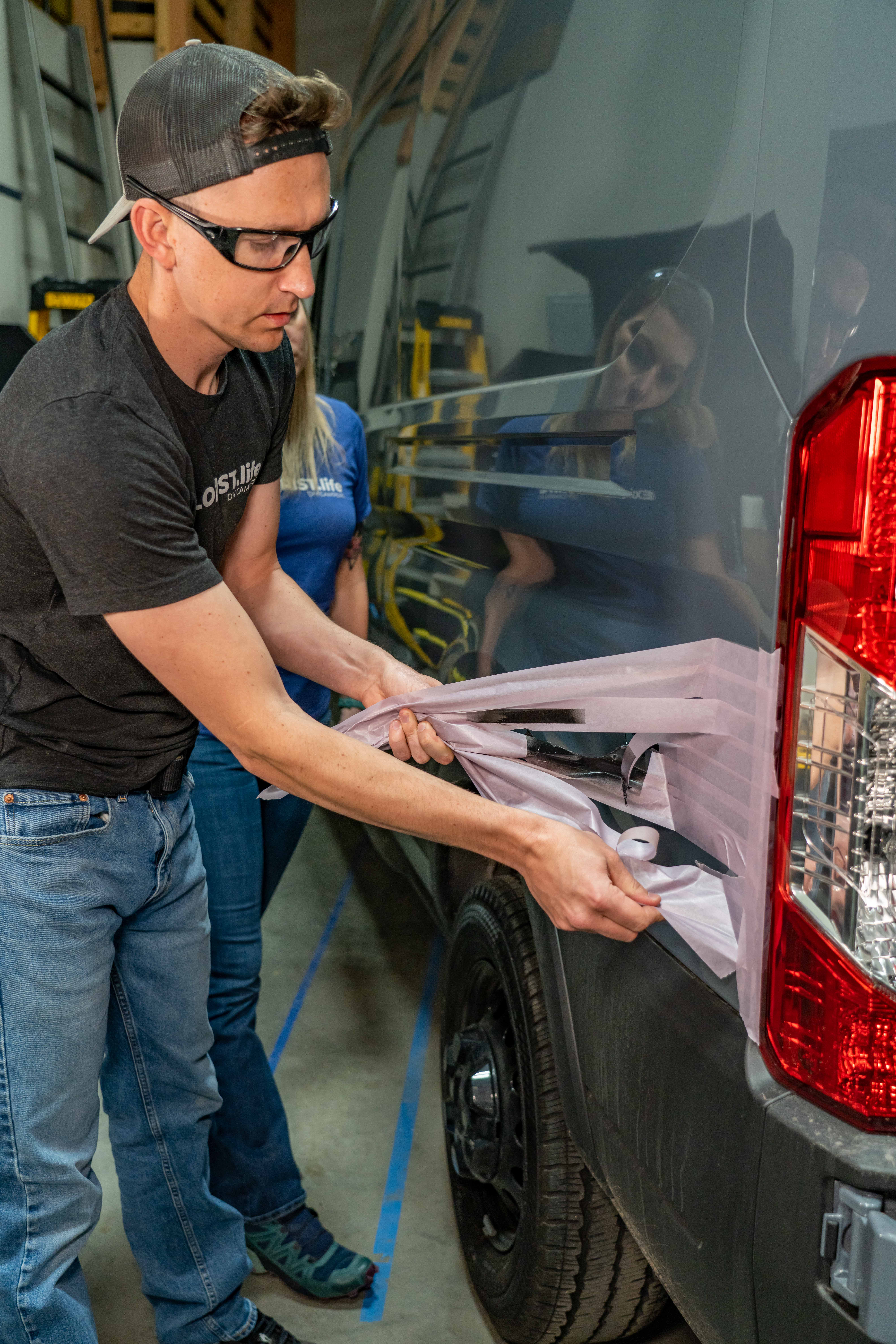
To protect the outside of the van from any kind of metal shavings, we covered the entire area with painters tape.
Drill Pilot Hole from Inside of Van
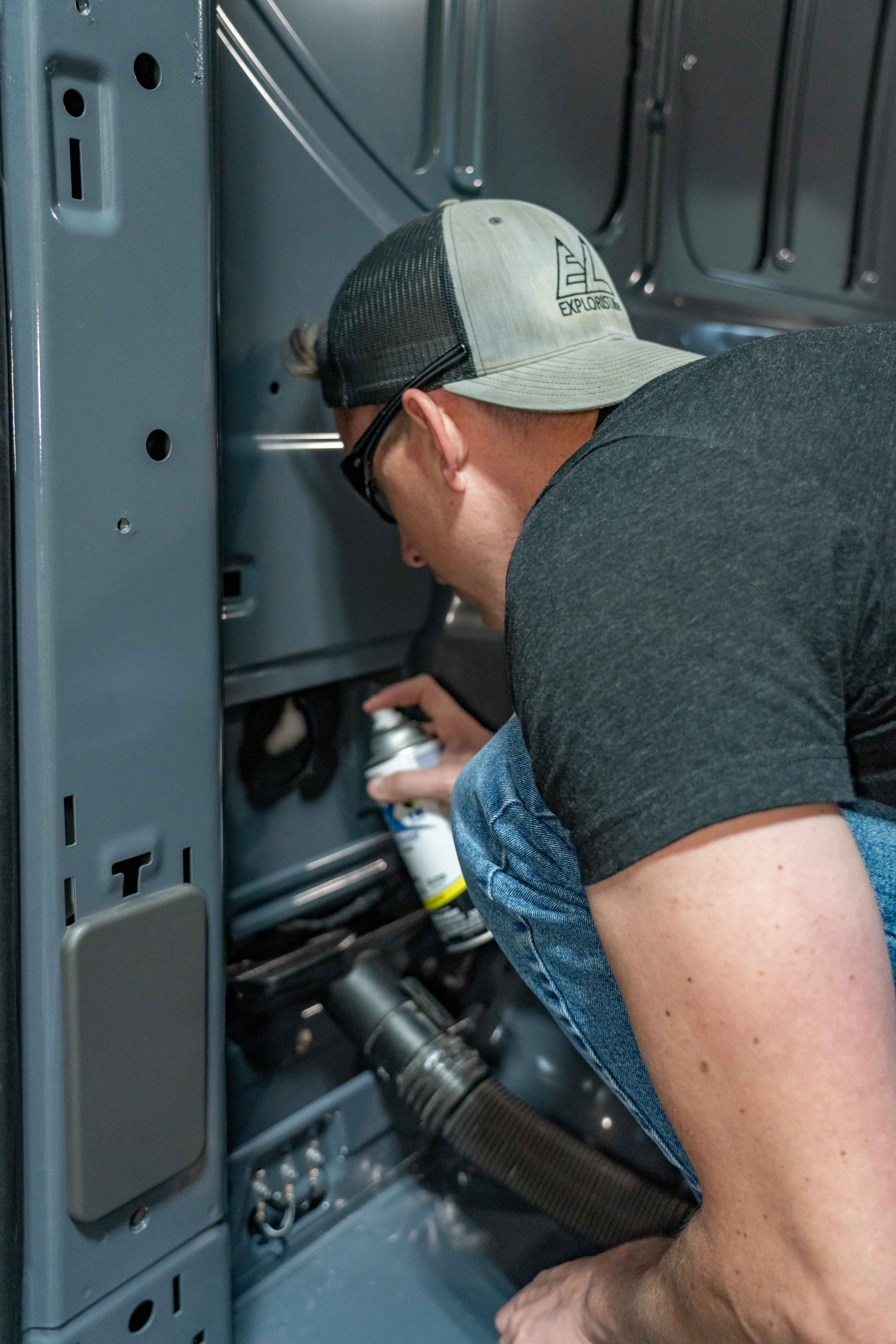
Then we drilled an 1/8th inch hole from the inside of the van with our cordless drill. We duct taped our shop vac nozzle to the inside of the van to be sure to catch all of the metal shavings. We drilled this hole from the inside so that we could be sure to give ourselves plenty of space from any of the body support ribs or any other obstructions inside the van.
Tape Box on Outside of Van to Catch Metal Shavings
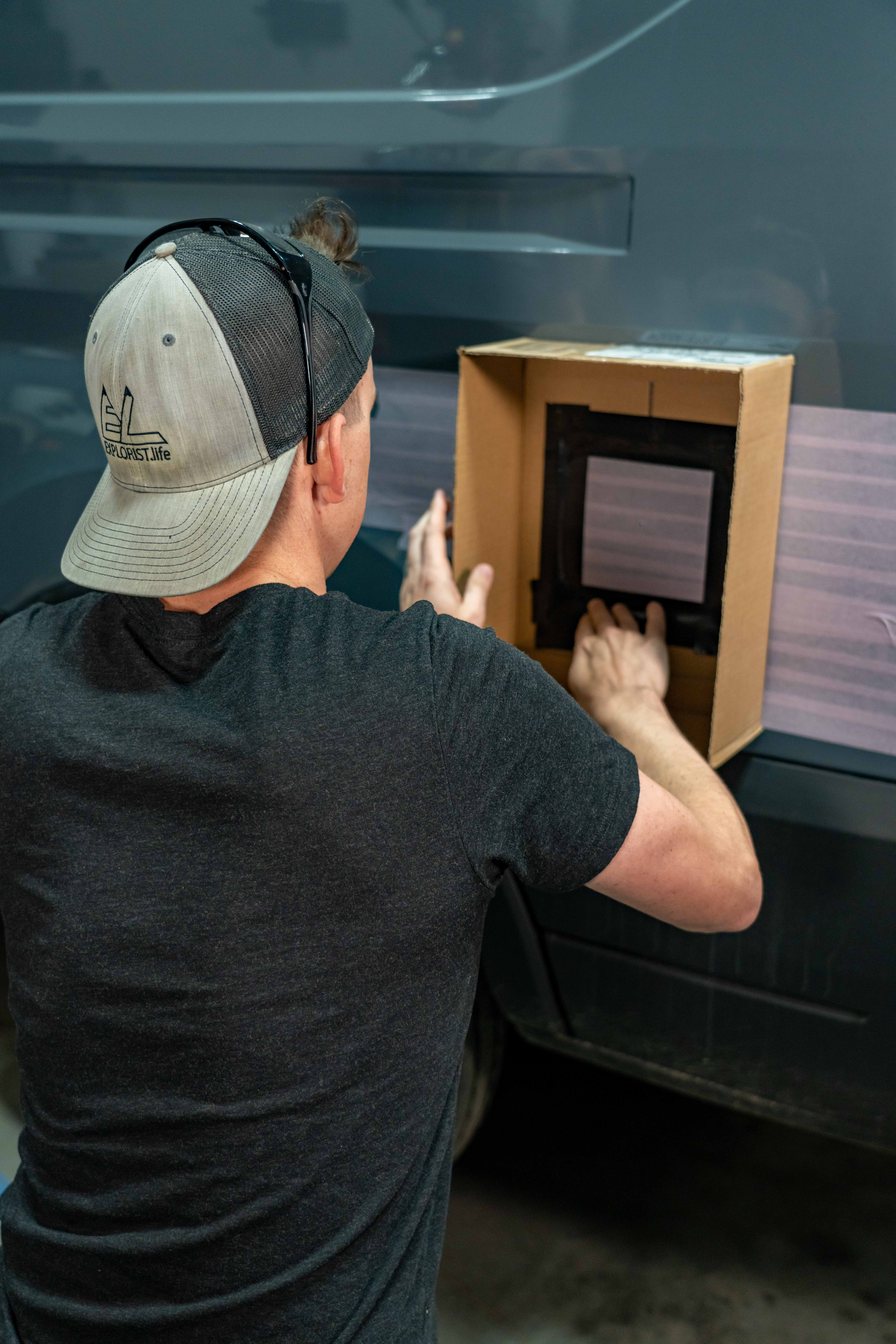
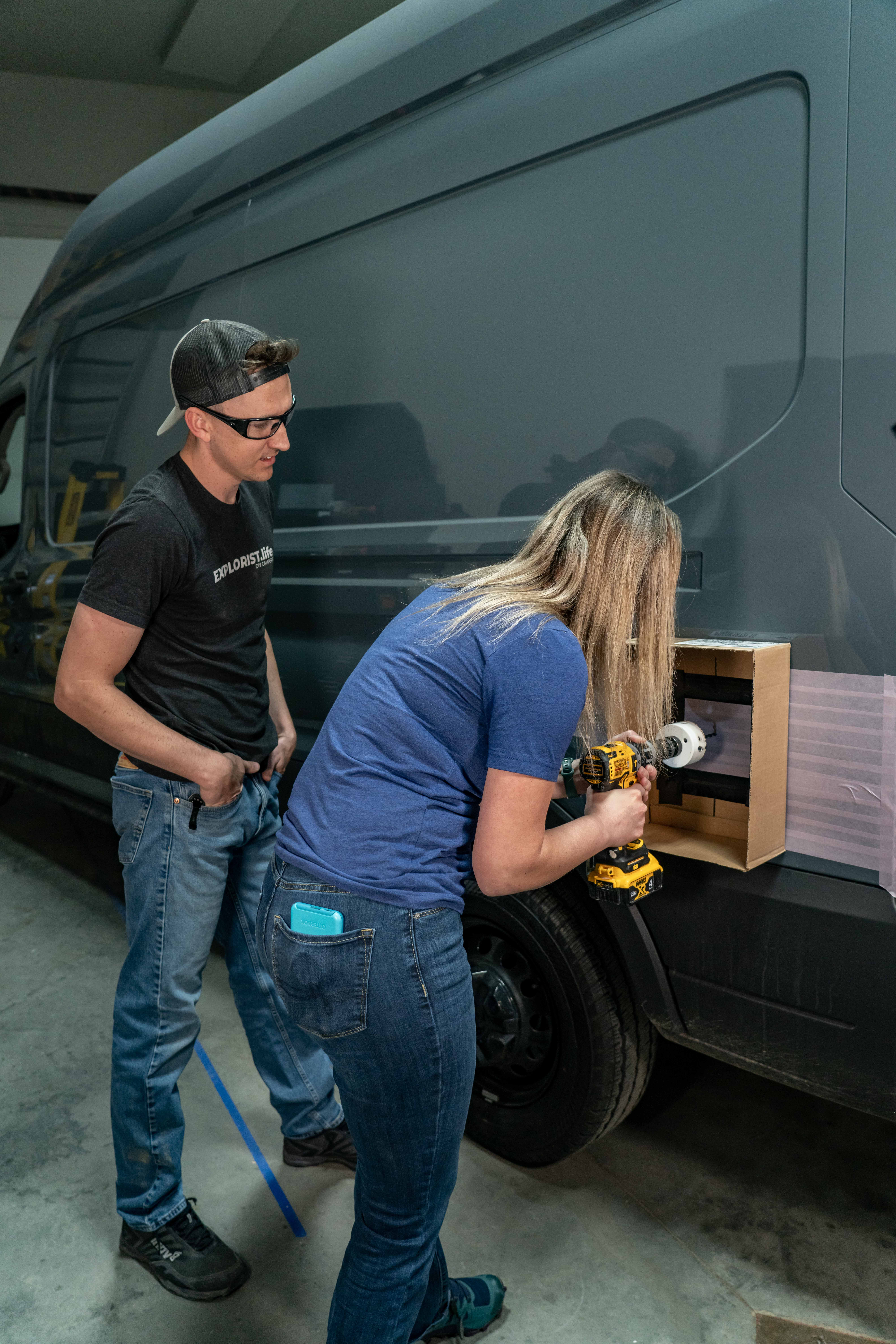
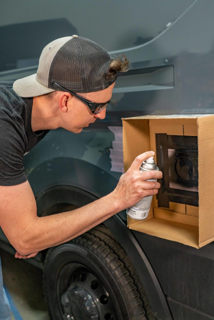
Then we moved outside and taped a box around where we will be using our hole saw to further control any metal shavings. If you’re not picking up on it yet… metal shavings are bad… They always seem to find their way into the most inconvenient spots and promote rusting.
Use a Hole Saw to Cut the Shore Power Inlet Hole
Next is hole saw time. We used a 2 and 7/8ths inch hole saw and VERY CAREFULLY started cutting our hole from the outside of the van. The metal of the van here is INCREDIBLY thin, so this doesn’t take very long. We didn’t use cutting fluid as this cut shouldn’t take long enough for the blade to heat up and it wasn’t worth the added mess.
Mark Screw Holes for Shore Power Inlet
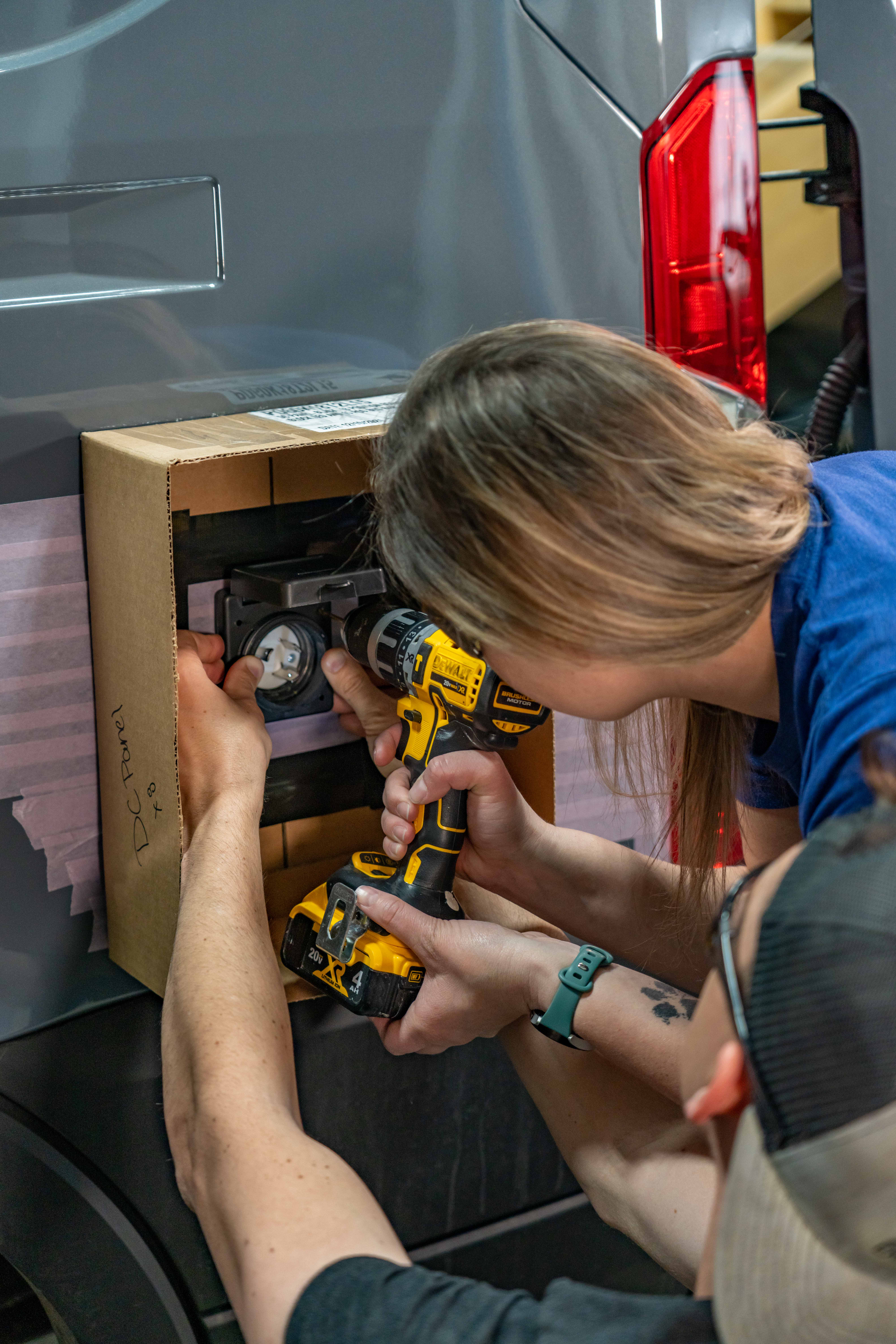
Now that our hole is drilled, we are going to take our shore power inlet and put it into the hole and line it up so it’s nice and level and then use our drill to lightly mark where the holes need to be in the van body. A mechanical pencil with some long lead or something would have worked better here; but alas… we didn’t have one.
Drill Screw Holes
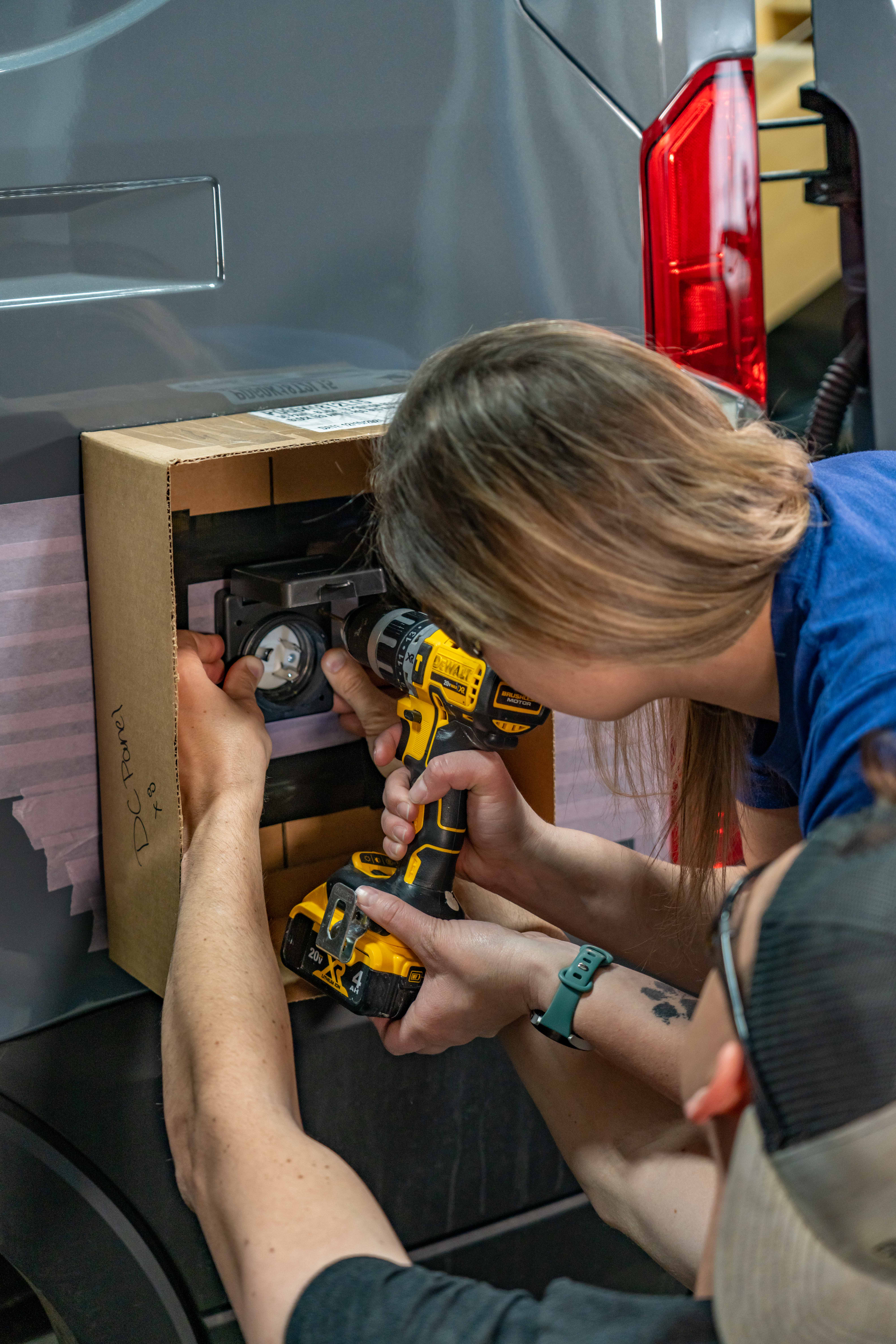
Next we used an eighth inch drill bit to drill the 4 screw holes…
Deburr Shore Power Inlet Hole
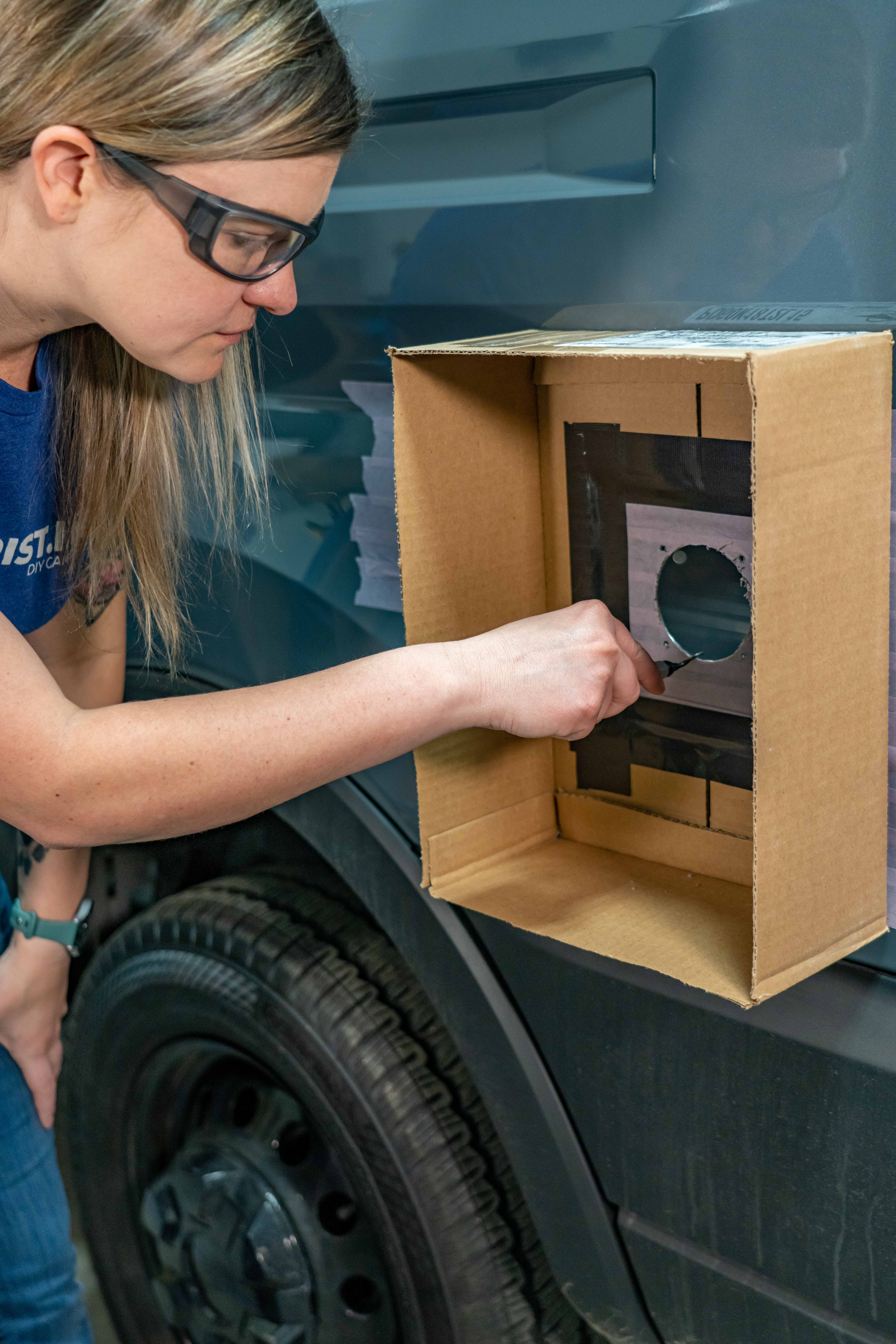
…and then a deburring tool around the bigger hole to get rid of any sharp parts or edges.
Treat Unfinished Edges with Paint to Prevent Rust
With all edges cleaned up, we held a piece of cardboard over the back of the hole and then sprayed a bit of rustoleum paint over the area we’ve been working on to cover up any exposed metal to prevent it from rusting. Then we did the same on the back side. We didn’t tape off the back since all of this will be covered up with insulation and walls, so we weren’t too worried about it.
Remove Tape and Clean Shore Power Inlet Area
Now that we were done making metal shavings, we could remove the box and tape from the quarter panel and carefully give the area, both front and back, a once over with the shop vac brush attachment.
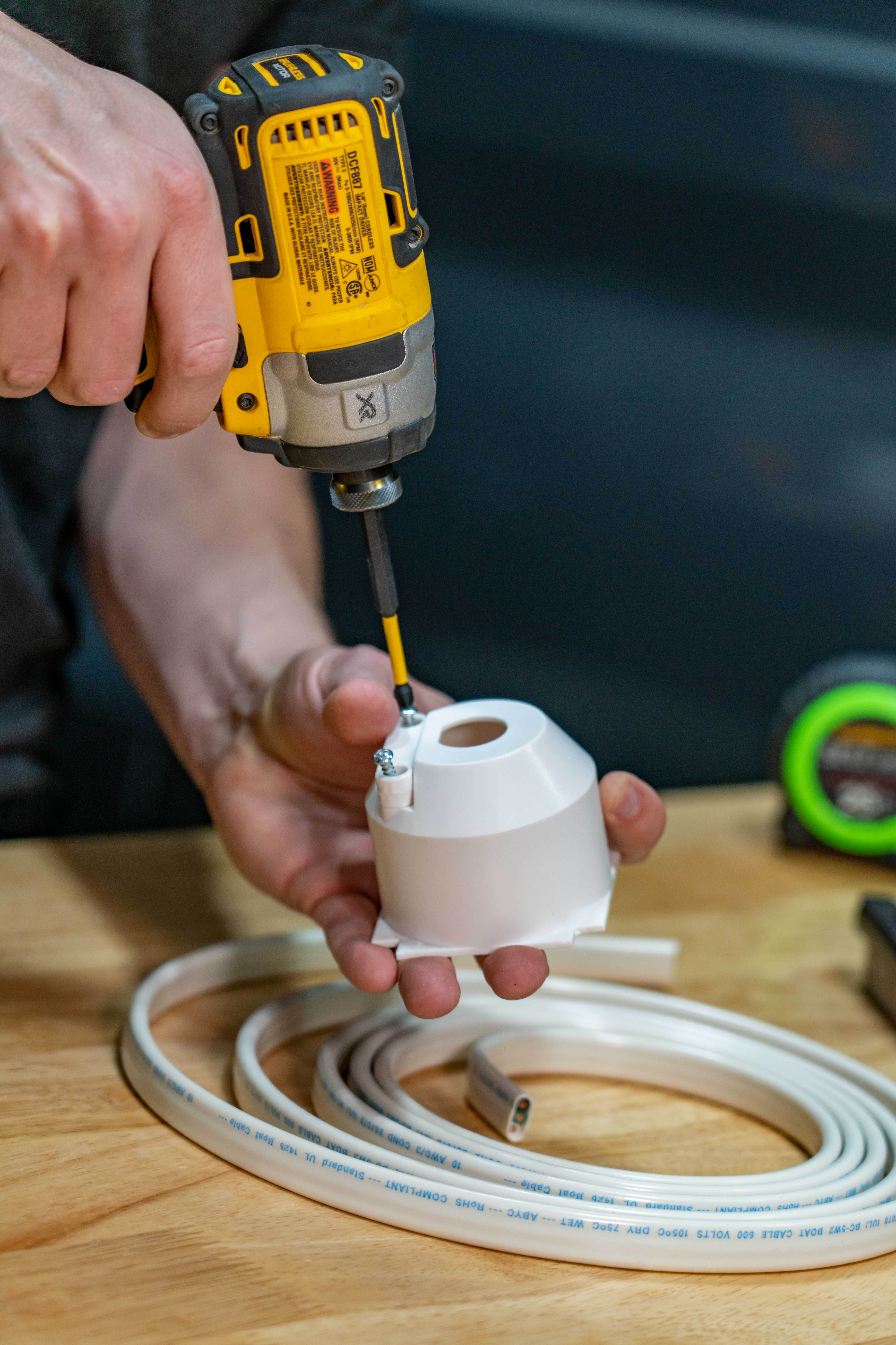
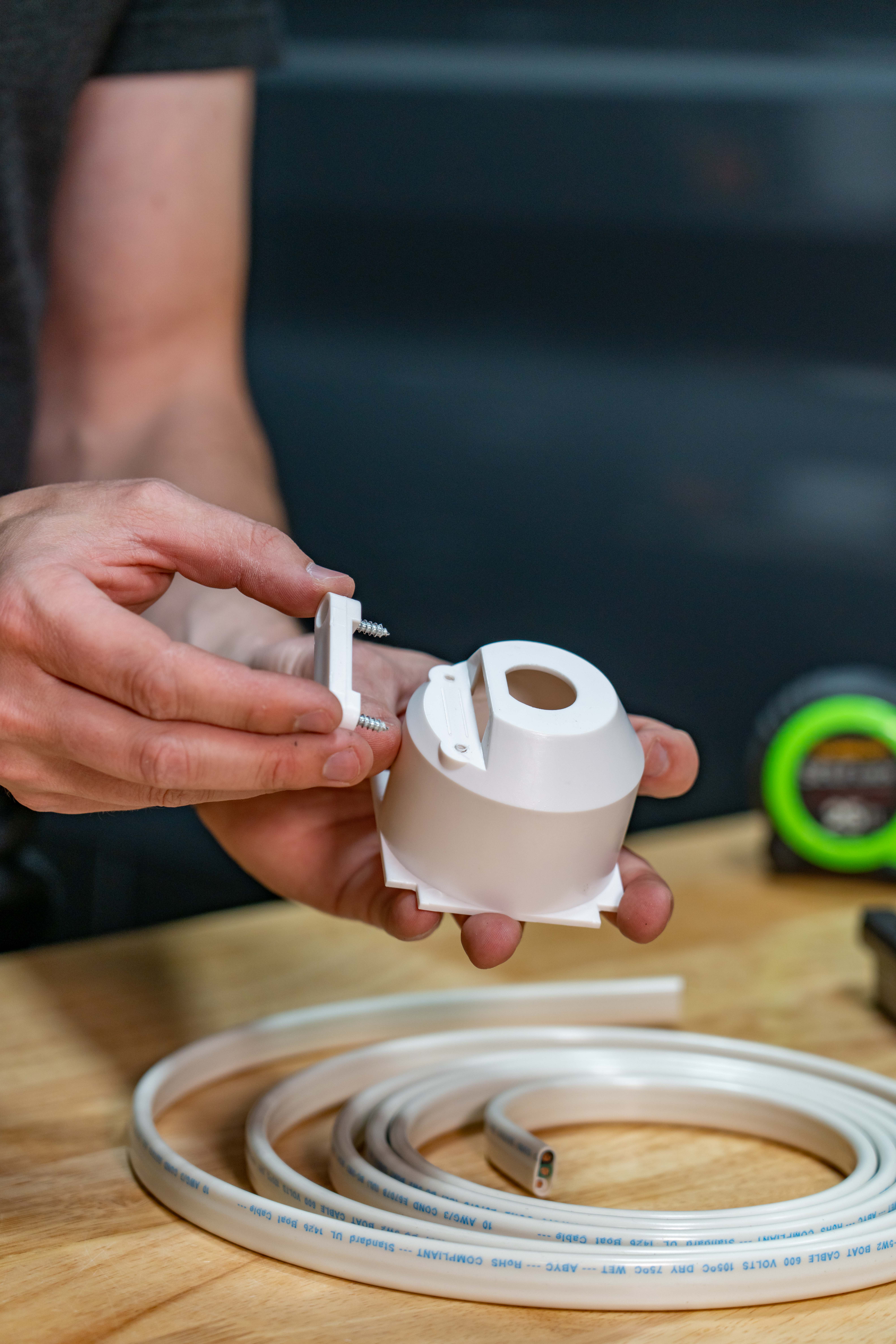
Remove Shore Power Inlet Retaining Clip & Insert Wire
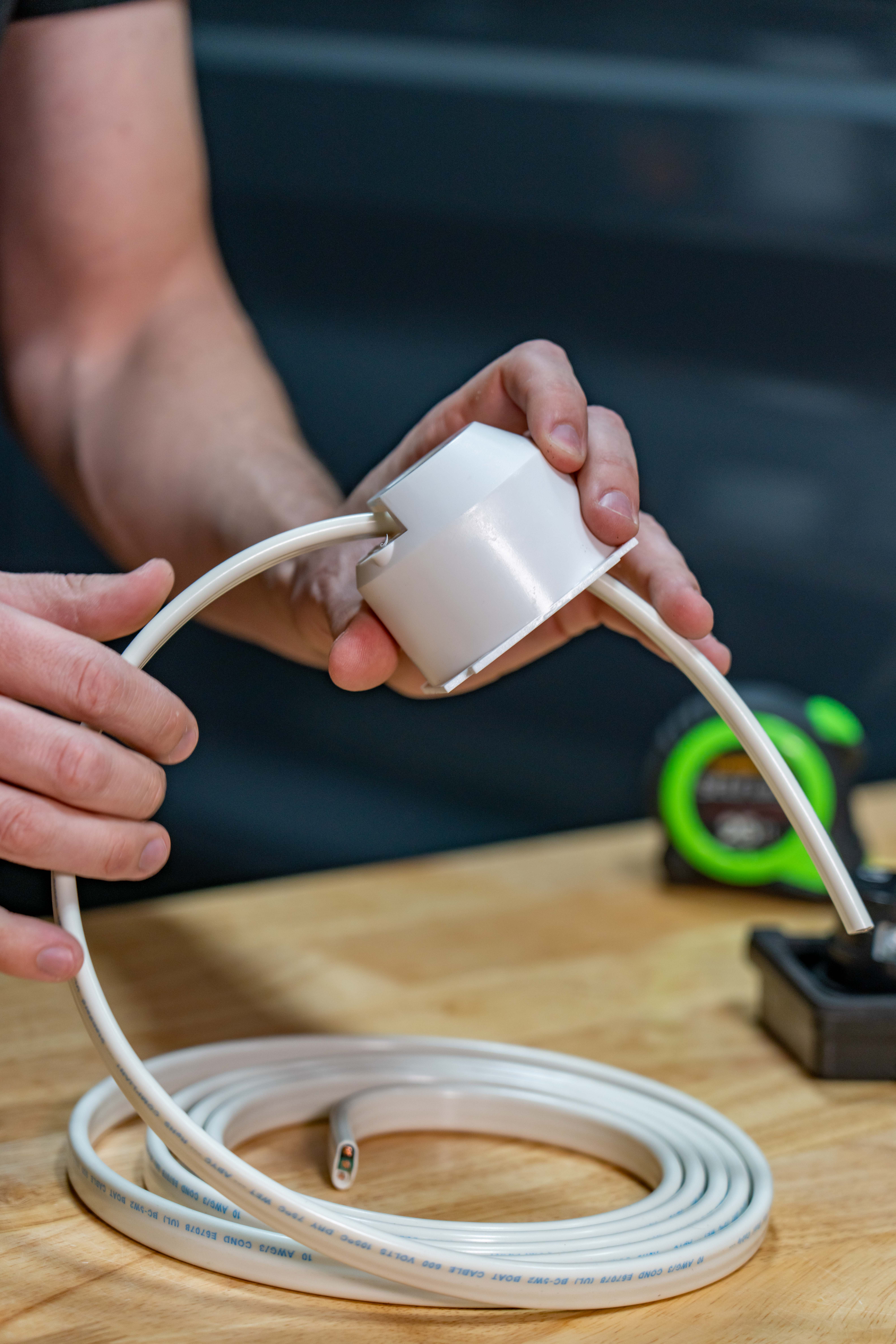
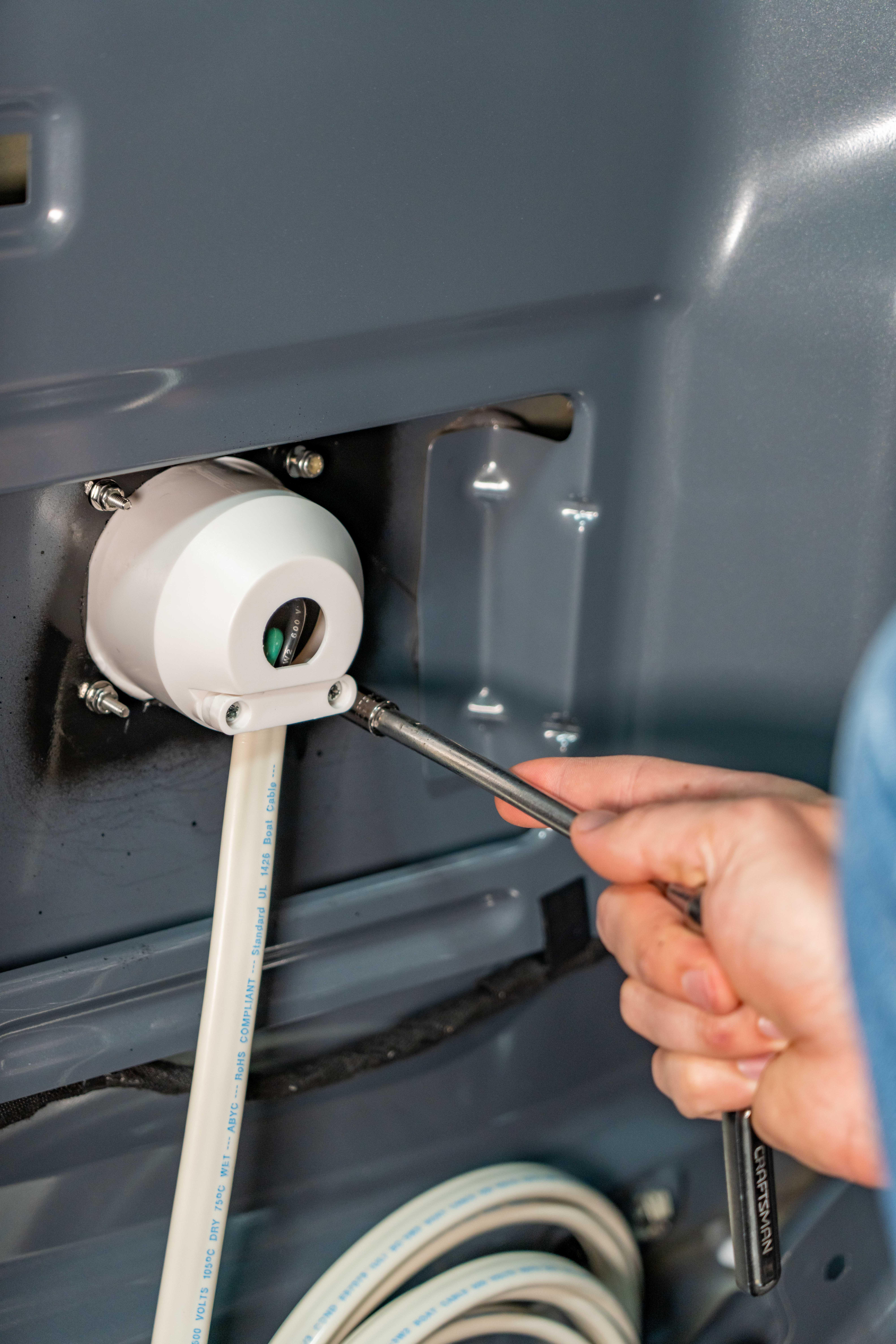
Next up we can wire the shore power inlet, so we’re going to remove the retaining clip on the back of the shore power inlet and then feed the 10/3 wire from the EXPLORIST.life 30A Shore power wiring kit through the back cover of the inlet.
Strip the Insulation from the 10/3 Wire
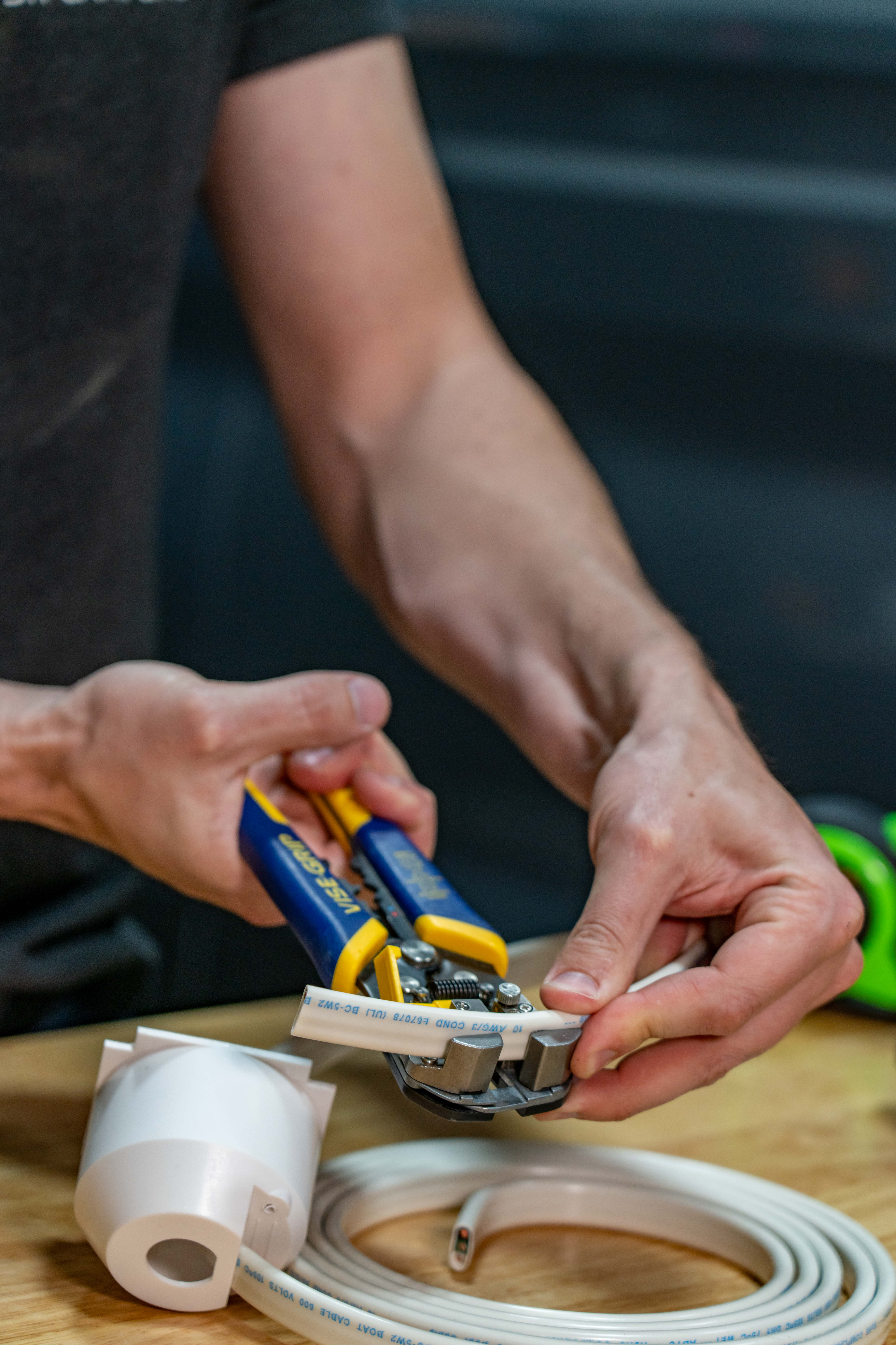
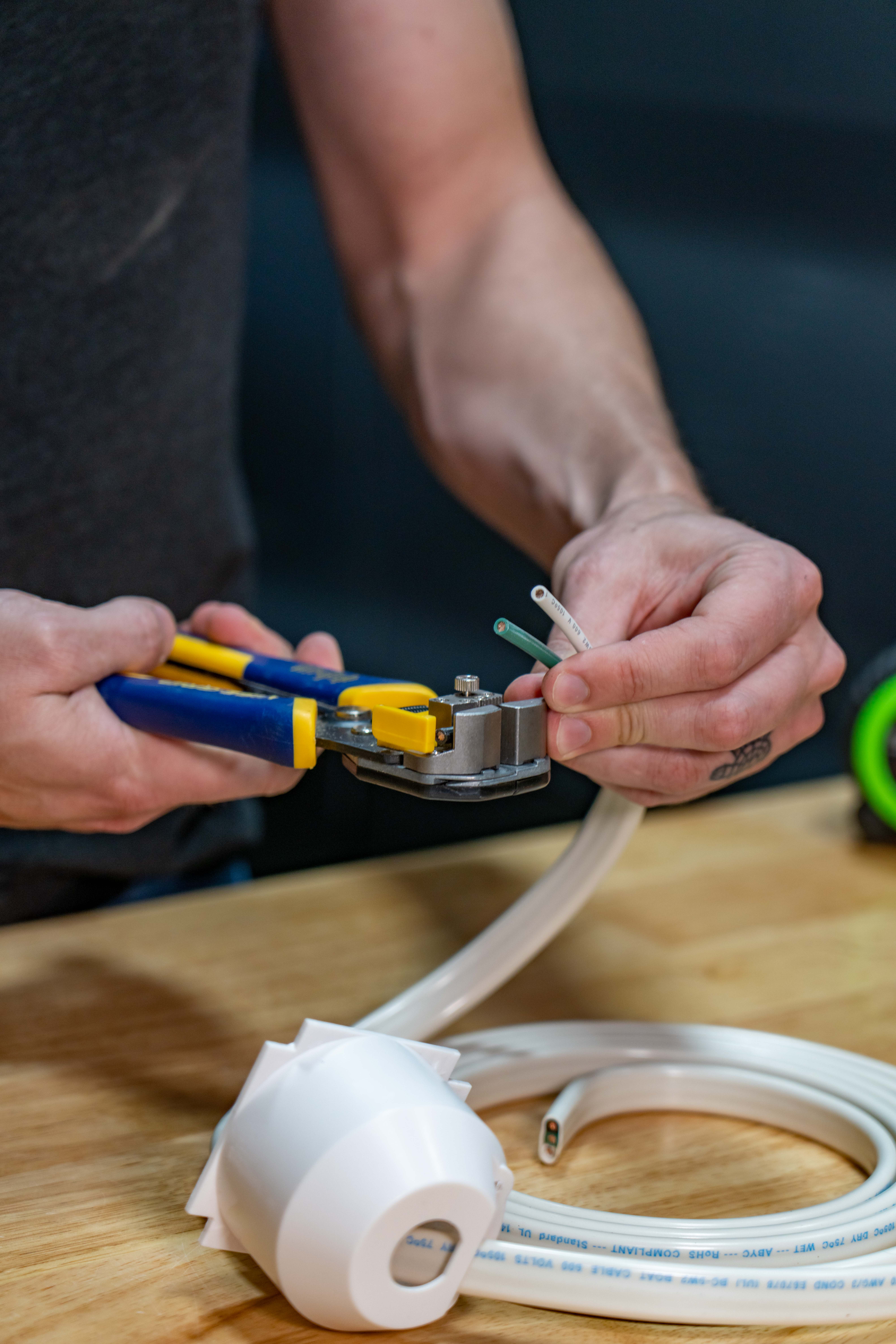
Next, we’re going to strip the outer sheathing back about 2 and a half inches and then strip 3/4 of an inch off of the end of each wire. Ferrules don’t fit particularly well in this shore power inlet, so we aren’t going to use them here.
Loosen Wire Terminals on Back of Shore Power Inlet
Next we are going to loosen the wire retaining screws on the sides of the shore power inlet.
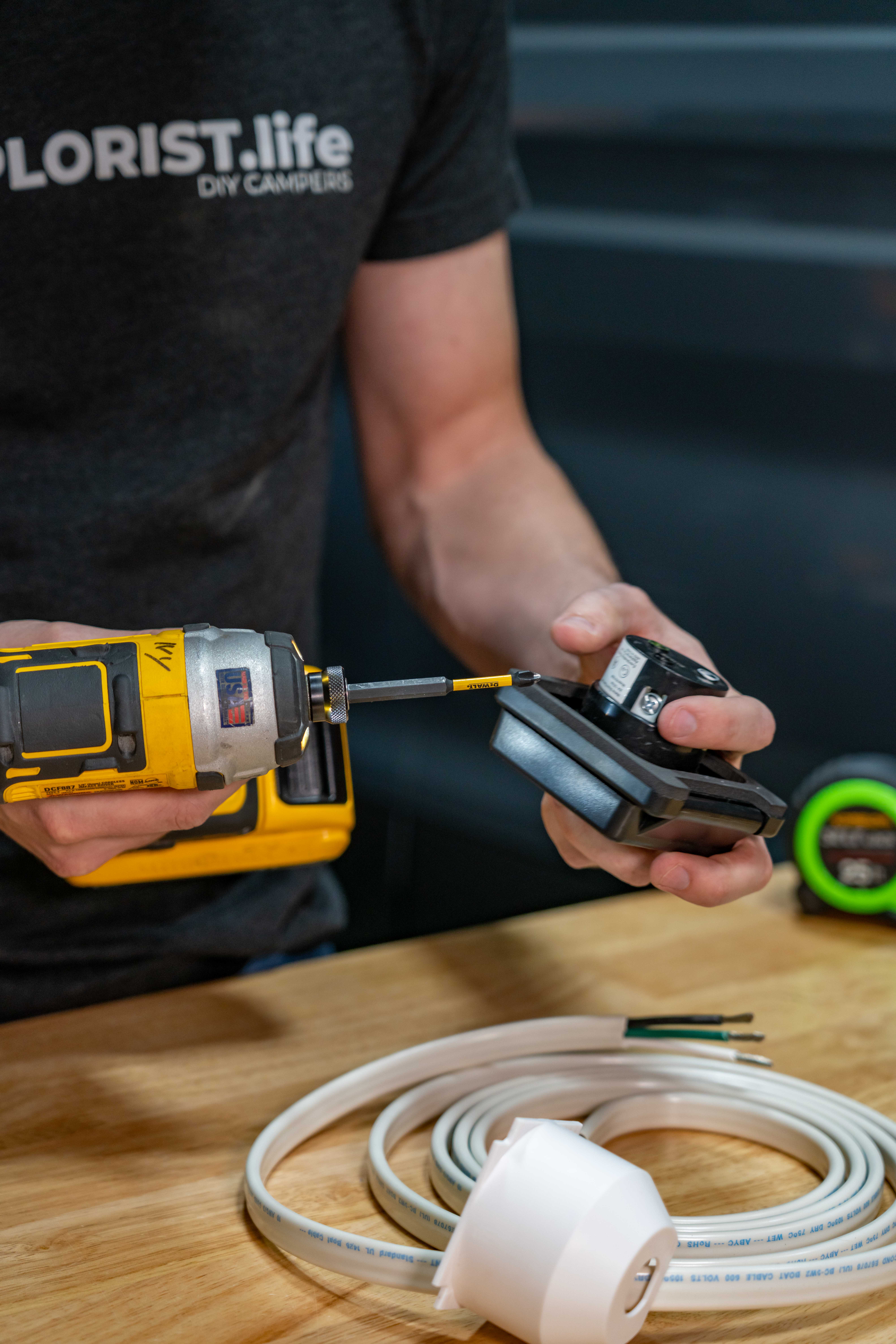
Insert the Wires into the Back of the Shore Power Inlet
Insert the Black, White, and Green wires into their respective color coded holes.
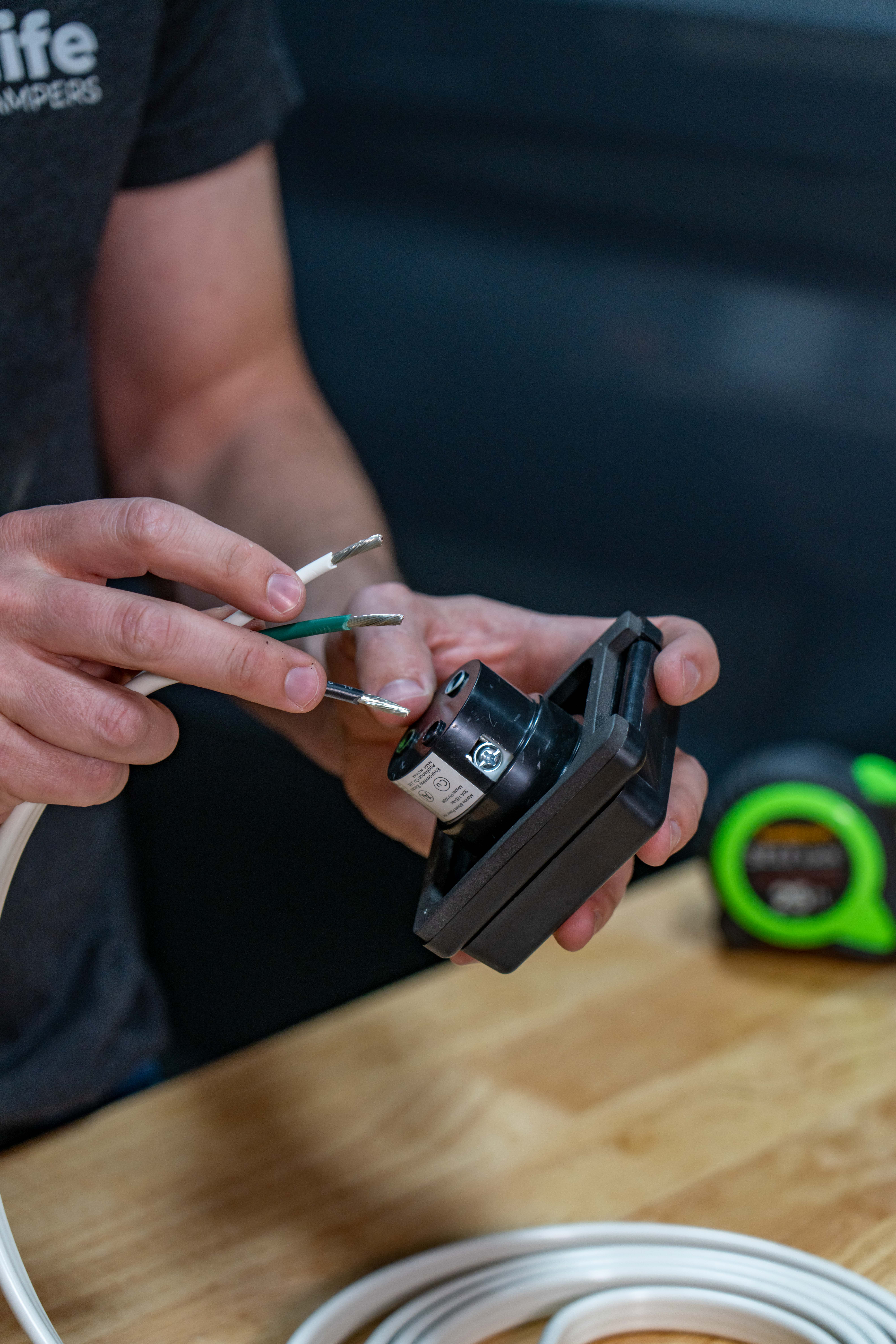
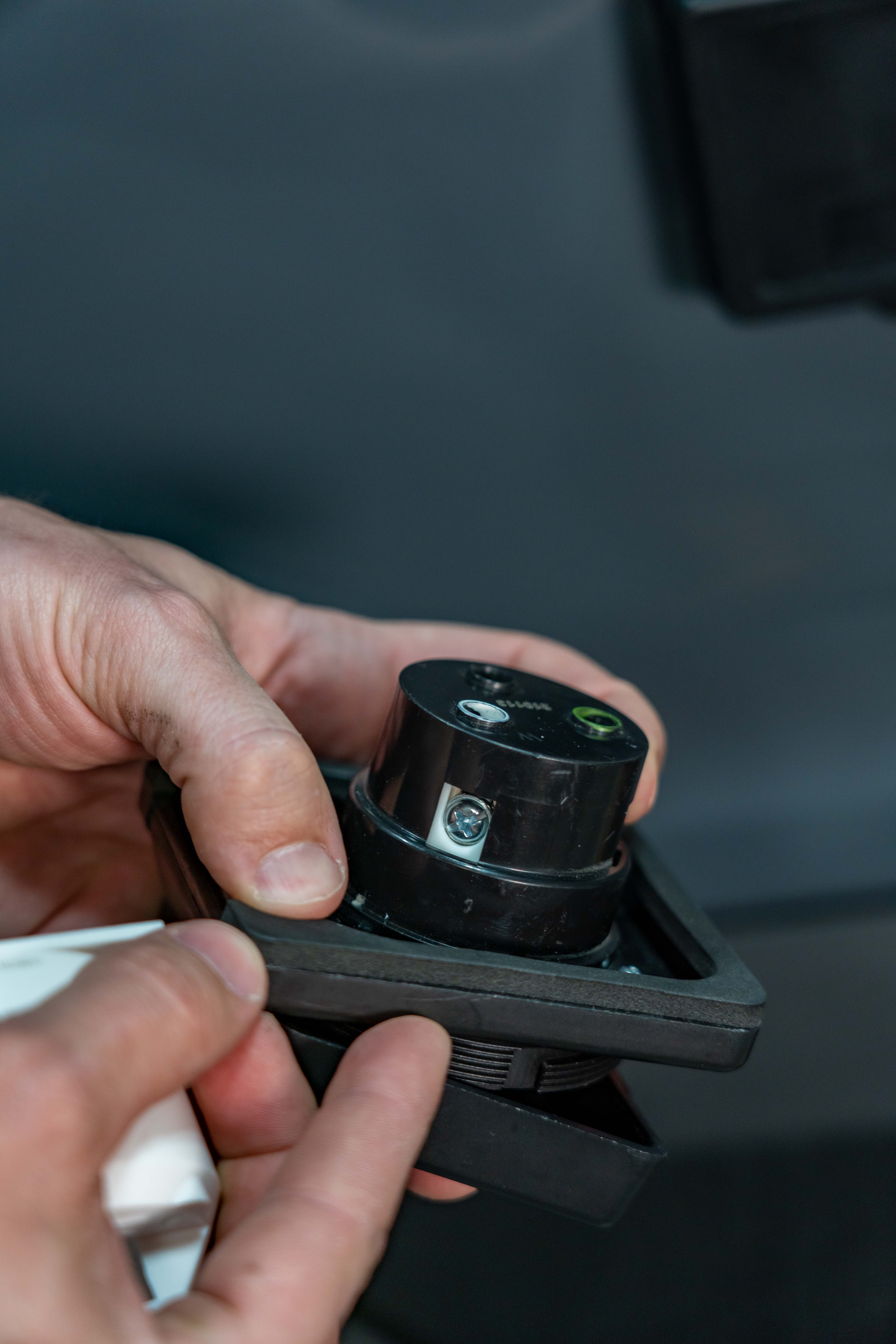
Re-tighten the Wire Terminals on the Back of the Shore Power Inlet
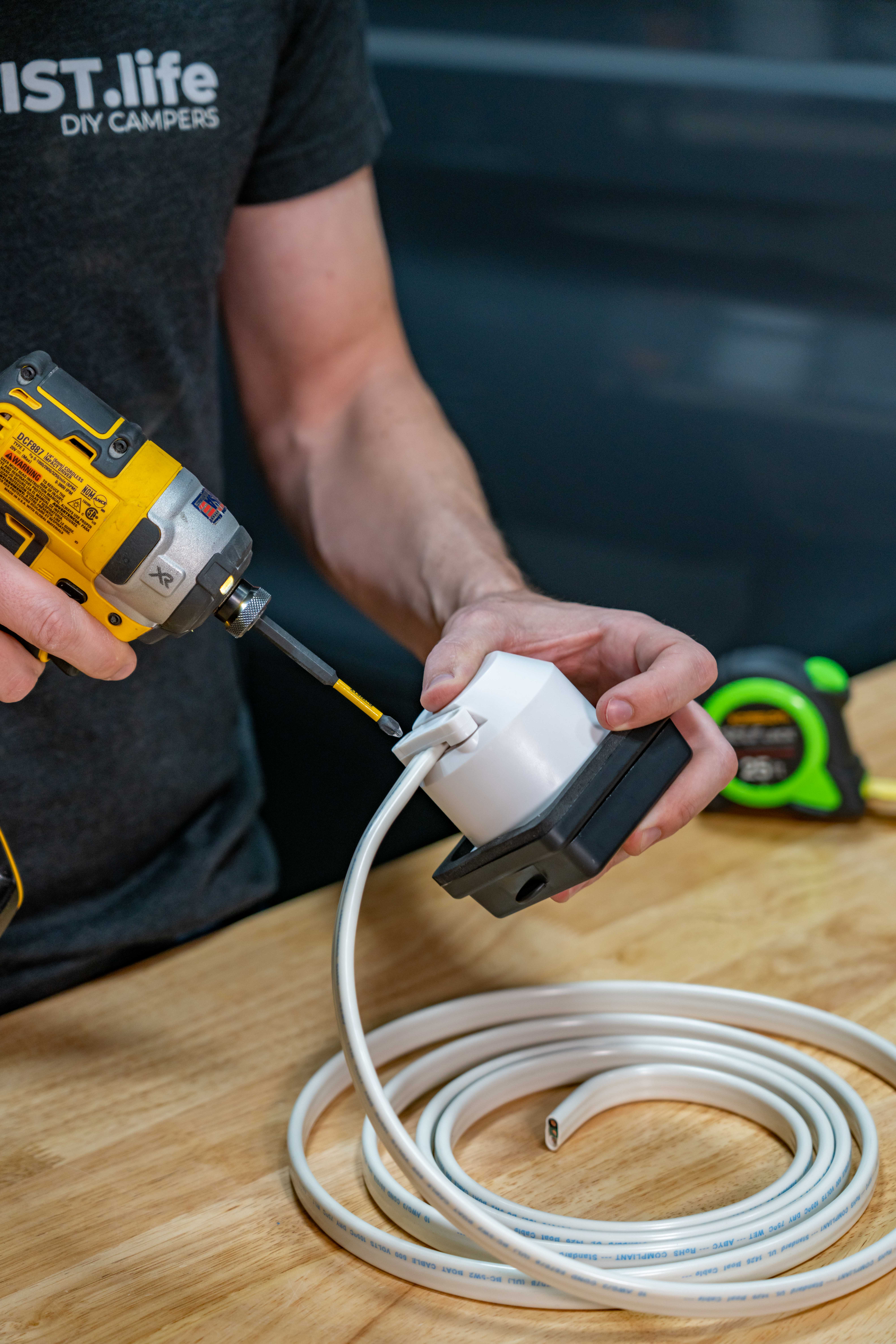
and then re-tighten the wire retaining screws to 20 inch lbs of torque making sure there is no insulation under any of the terminals creating a poor connection.
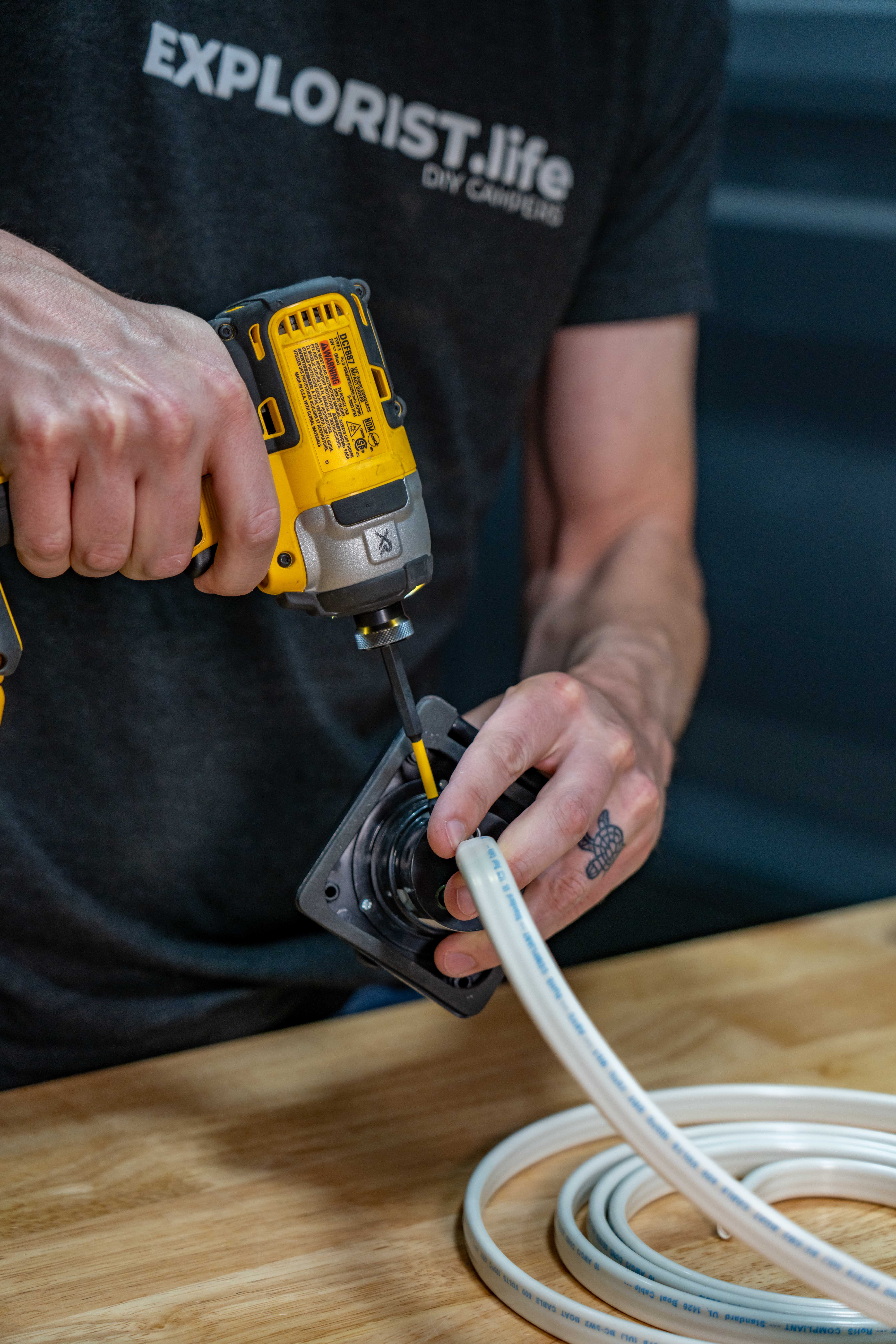
Put Shore Power Inlet Housing in Place
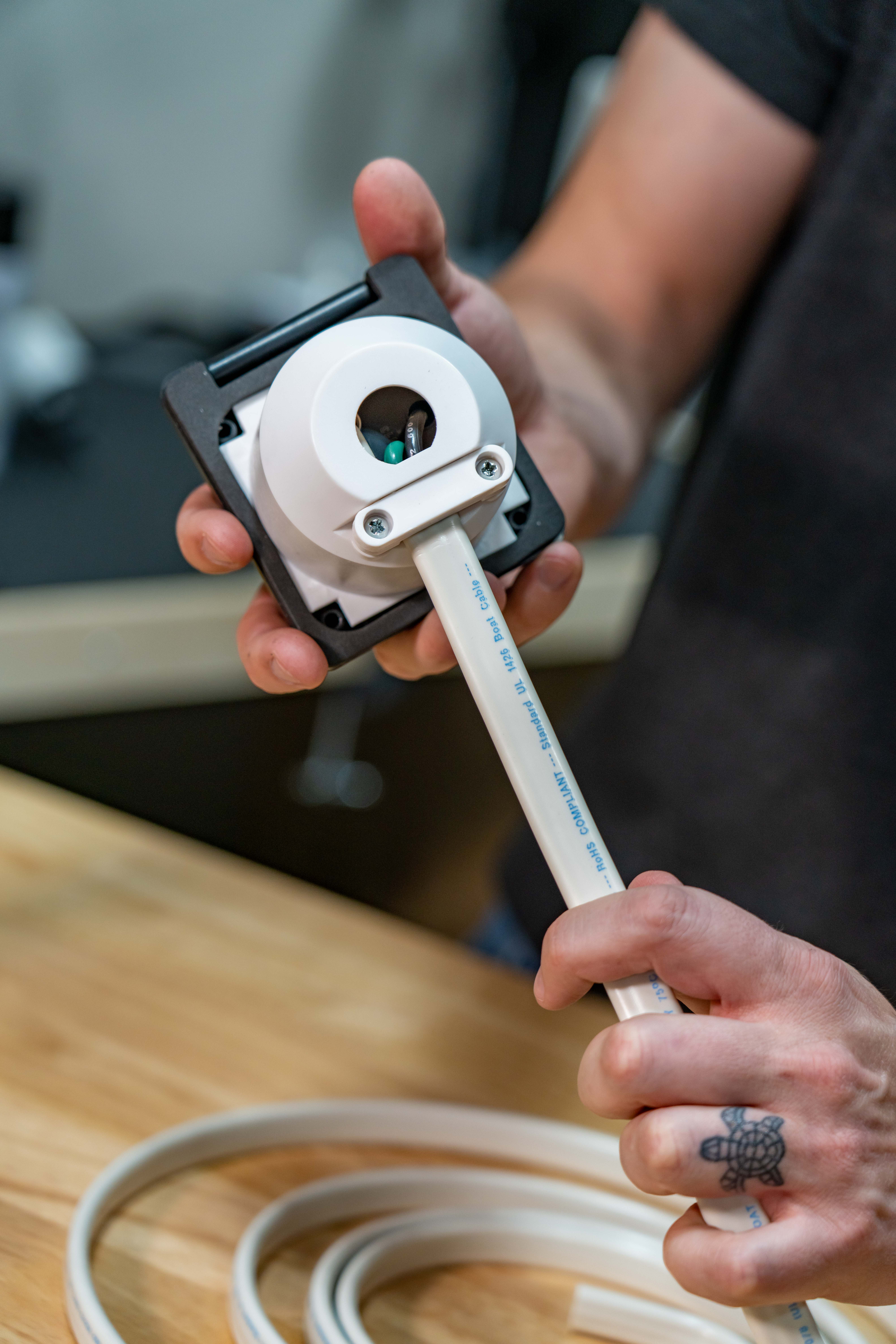
Then we can slide the shore power inlet rear housing up the wire and then put the retaining clip back back in place.
Fasten Shore Power Inlet to the Van
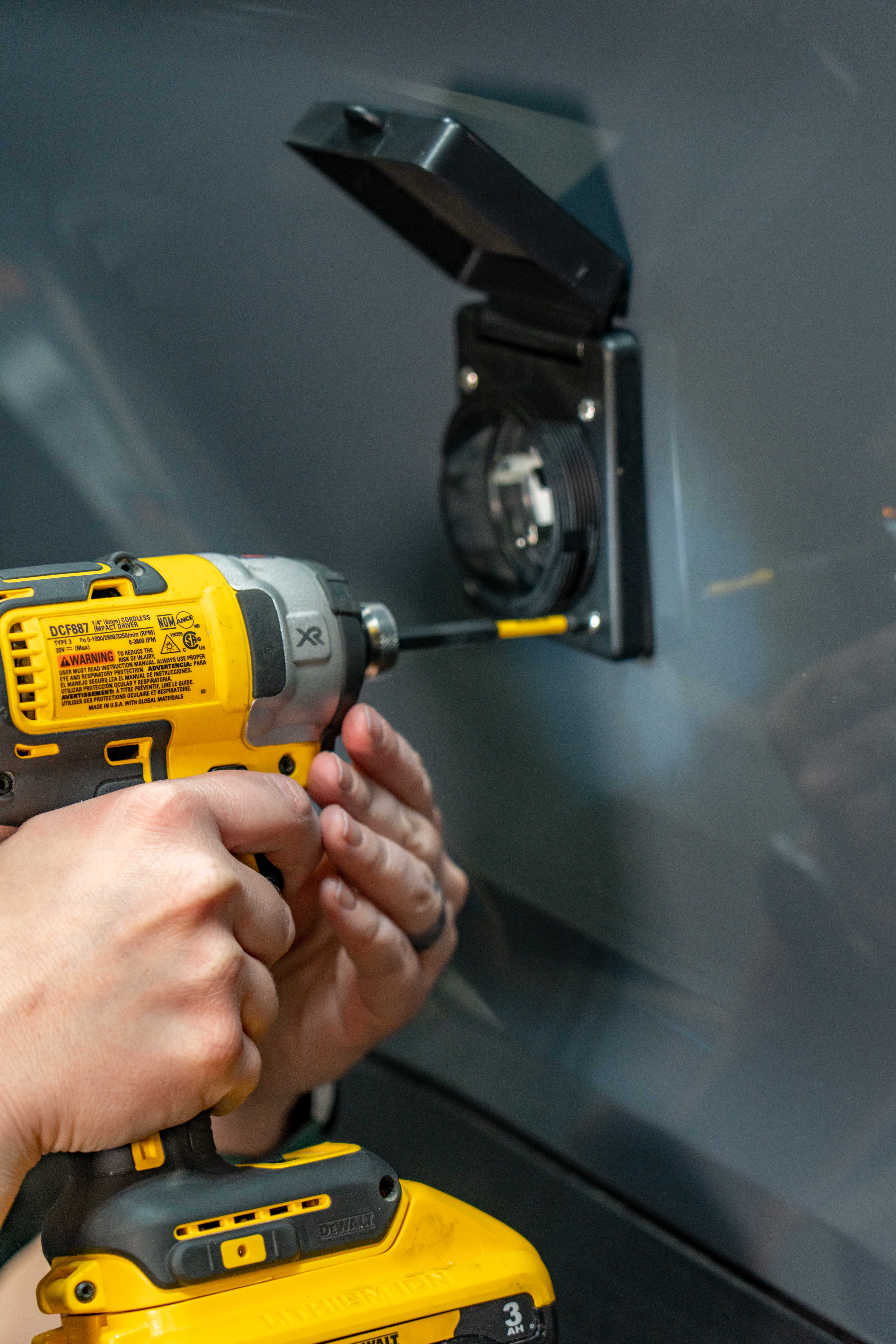
Next we are going to fasten the inlet to the van by placing the inlet in place, putting our 1 inch #8 stainless steel pan head screws into place, and then threading our washers and nylock nuts on the back and tightening them until they are snug.
Waterproof Gasket Already Installed
The back of this inlet has a waterproof gasket pre-installed on it, so no additional sealant should be necessary; but if you are mirroring this installation and don’t trust the seal, feel free to add a bead of dicor sealant around the perimeter.
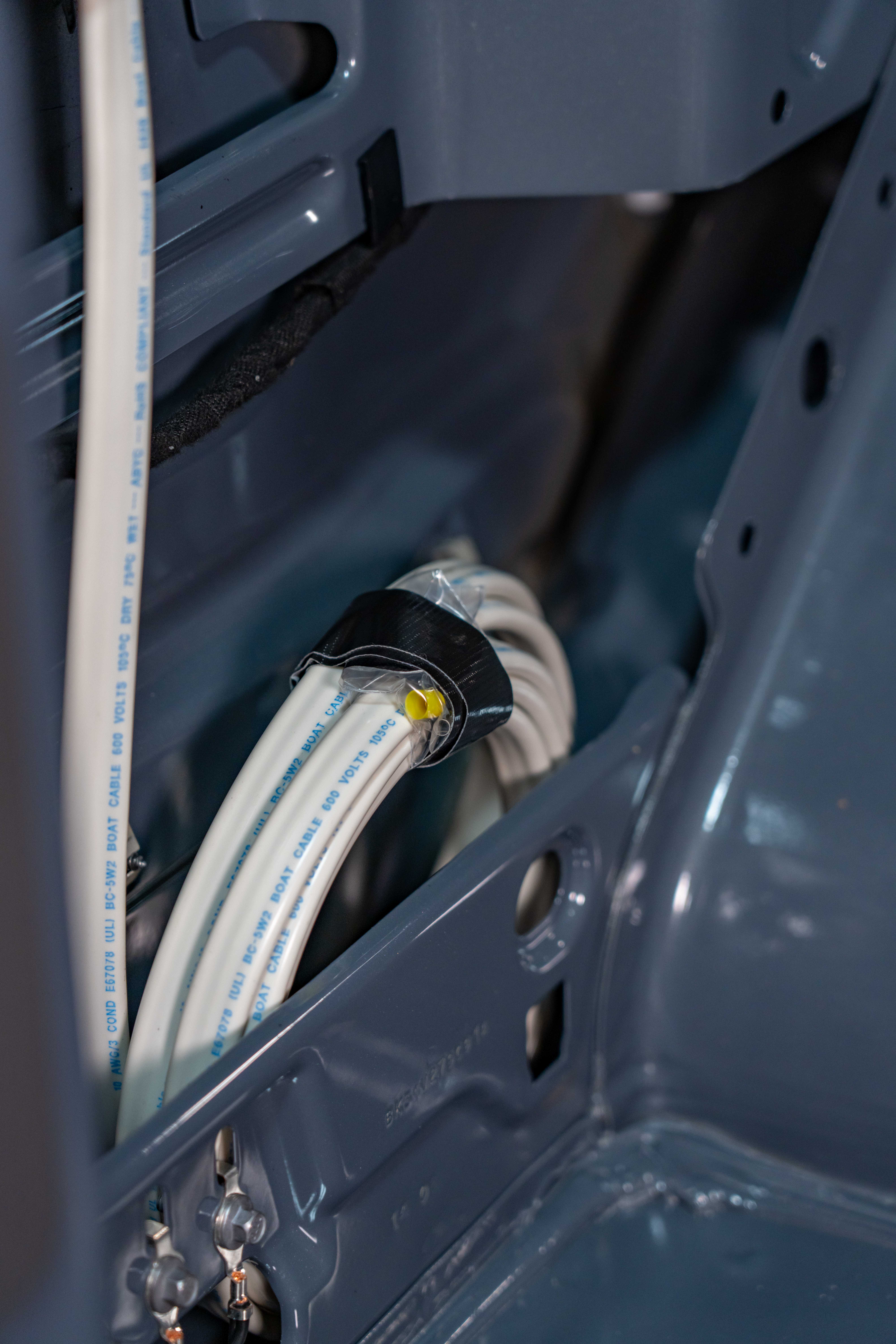
Coil Wire & Save Ferrules for Later
The ferrules that were included in the wiring kit from this installation will go on the opposite side of this wire when we wire this inlet to the Victron Multiplus Inverter Charger later in this series, so I’m just going to tape this baggie to the end of this wire and coil the wire up for safekeeping for later.
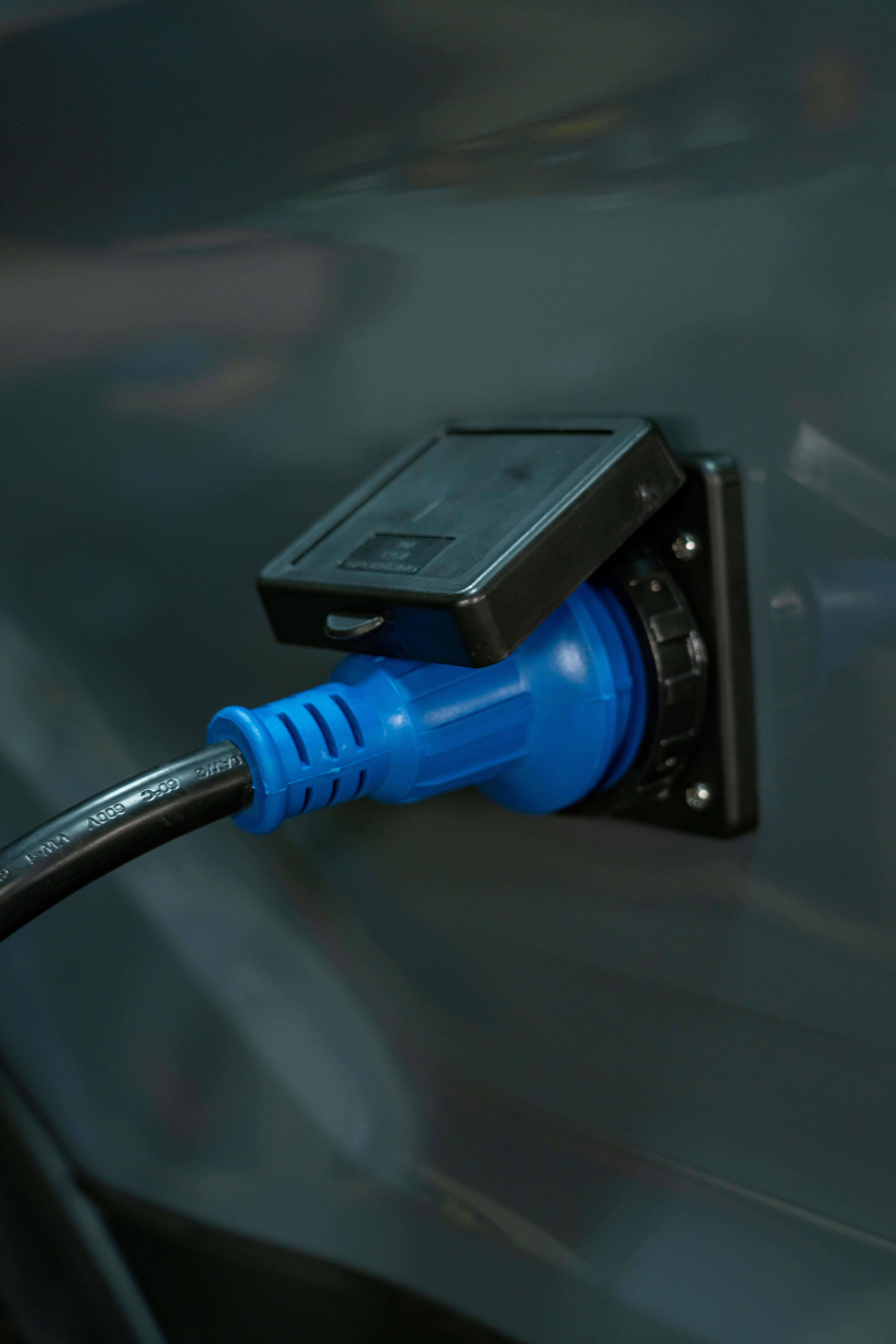
Installing a Shore Power Inlet in a DIY Camper Van – Finish
And that’s all there is to it! The shore power inlet is now installed and could technically be connected to a 30A shore power inlet at a campground or to a standard 15A household outlet by means of a 30A to 15A adapter… but don’t connect that yet… remember… The other end of the wire in the camper is not connected to anything so we don’t want to send power to it.
Now that we have the shore power inlet installed in the side of the van, it’s time to move on to the next step in this series. We need to remove the headliner of the van to start making access to as much of the metal of the van as we can so we can start getting our plan together for sound deadening and insulation…and that’s coming up next.
Now, we hope you found this blog post helpful, and if you did; it’d be awesome if you’d share it with somebody, or a group, who you think could use it. Leave any questions you’ve got or new things you learned in the comments section below. If this video inspired you to build something, be sure to tag your projects with the EXPLORIST.life tag on instagram so we can see and share YOUR projects. Subscribe if you want to see more DIY camper building tutorials and we… will see you next time.

12 Responses
Hello Nate and Co! Thank you in advance for such an amazing resource database. Question about your 2000w DIY interactive diagram: “2000w INVERTER | 200-400Ah Lithium | 200 TO 700W SOLAR Camper Wiring Diagram”
Can one simply delete the charging from alternator portion of that diagram, leaving the only charge sources being shore and solar?
Thank you!
GB
Yep! Sure can!
I have since discovered Nomadic Cooling 2000 and 3000 and the Dometic RTX 2000. Those seem to be popular in the van community. If you have recommendations other than those please let me know. Thank you.
Great options! We will be installing a 24V Nomadic 3000 in our new Transit build series: https://www.youtube.com/watch?v=iga8VotrDqg&list=PLmvhcyi4n0TVfA4XCYJBkzfUXunSON1zX&index=1
Hi Nate. Do you have recommendations for roof-top (or some other form factor) air conditioning in a van? I use a 120v LG mini-split on my travel trailer because I have the room for it. I have seen DC roof-top air conditioners in the past but they are very, very expensive. Someone I know asked me what I think for her Winnebago Era (Mercedes Sprinter chassis). She has doors in the rear that she uses so mounting a 120v outside compressor unit is a no-go, not to mention the precious little wall space for mounting the air handler. So I bring my dilemma to you for any recommendations you might have. Here in the midwest it’s both hot and humid in the Summer months and she has dogs she’d like to keep safe inside the van. Any thoughts?
Thanks in advance!
Hello Nate,
We’re following your transit build on YT with interest as we plan to receive our 22 in a couple of months. What is the max charging rate from the Ford dual alternators that your system setup below will allow?
3000W Inverter Charger
400+ Amp Hours of Battery Storage Capacity
400W-1200W Solar Array Capacity
Alternator Charging
Shore Power Charging/Passthrough
You and Steph are sharing high quality videos, thank you so much !!
R/ Mike
I’ll have you ‘stay tuned’ for that answer. 🙂 We will be releasing a video specifically about alternator charging once we get to that point in the build.
Nate
I have downloaded the first wiring diagram on your Wiring Diagram page to get further detail to help me with my Sprinter conversion.
I am planning a simialr system to that in the first diagram (200Ah of Lithium batteries, Solar, DC-DC charging, multiple 12V loads, shore power for charing and AC scokets, but with no invertor).
I wonder how my setup would change with the removal of the invertor?
Thank you for the great content.
Richard
p.s. Sorry if this comment appears twice. I typed it and lost it the first time!
There would be a LOT that would need to change and you would end up with a sub-par system. You MUST have shore power for a well-rounded system as shore power is ‘guaranteed’ and is vital for, if nothing else, troubleshooting and commissioning.
Hi Nate,
I’m planning a trip this summer from San Diego to Yukon CA to Nova Scotia CA to Virgina (grandkids) to San Diego. We are driving a 30 Amp 2019 Coachmen Prism that you helped a lot with wrt solar (1KW), Victron, batteries (500Ah) etc. I installed a Progressive Industries EMS HW30C.
Constructive paranoia tells me that I may need to plug into a 50 Amp RV pedestal in the case of a broken or absence of a 30Amp outlet…AC will be nice crossing the US to home in July!
I can connect to a pedestal using a male 50A/female 30A adapter but it has no “over current protection” since at the output there will be 110V/50A power. The adapter has no circuit breaker. That leaves the line from the pedestal, to the side plug in to the internal power panel main breaker unprotected from over current…the EMS handles surges and other voltage issues.
So I’m thinking of adding a breaker at the point of entry plug and wonder if you considered this in your van conversion plans.
Best,
Chris
I’ve never seen a campground power pedestal that has 50A but does not have 30A. I also wouldn’t worry about a ‘broken’ 30A shore power outlet… If the 30A outlet is ‘broken’, I wouldn’t use the 50A in the same pedestal. I think this scenario is a non-issue.
Can’t tell you how grateful I am! Loved the photo blog. Makes it soooo easy for this 65 year old grannie who is doing my own van conversion on a Ford Transit high roof. You guys are the best.