The amps and volts of a solar panel array can be affected by how the individual solar panels are wired together. This blog post is going to teach you how the wiring of a solar panel array affects it’s voltage and amperage. The key takeaway to know is that ‘Solar Panels in Series Adds their volts together’ and ‘Solar Panels wired in Parallel adds their amps together.’
Tutorial Video:
Solar Array Volts & Amps Wiring Diagrams:
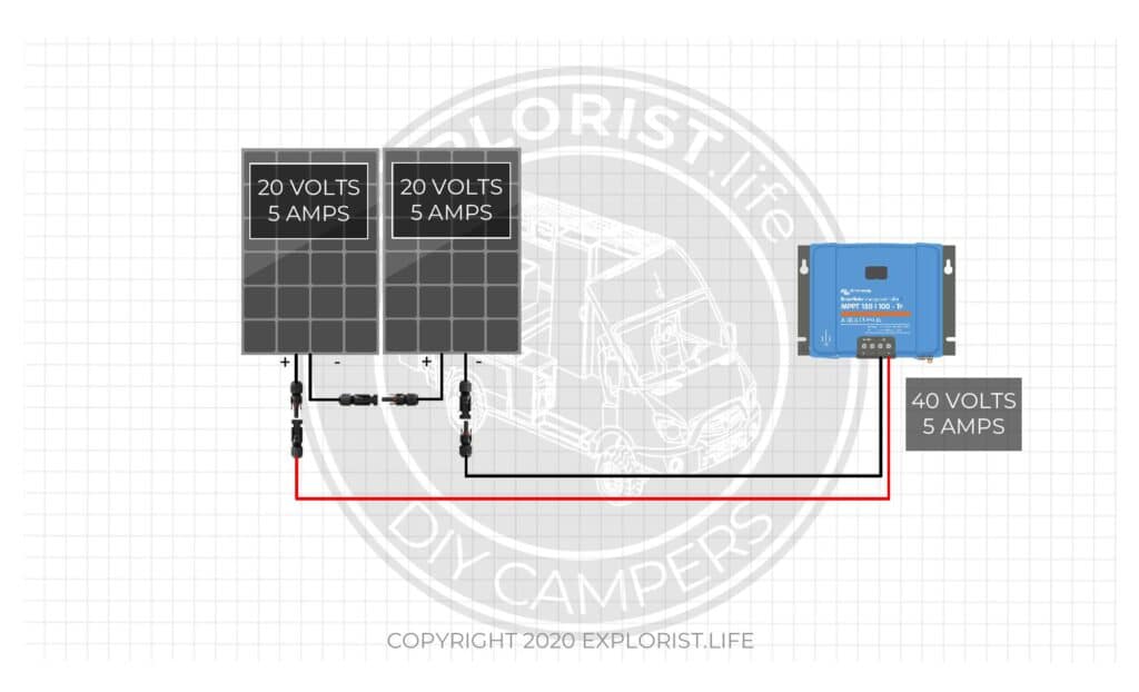
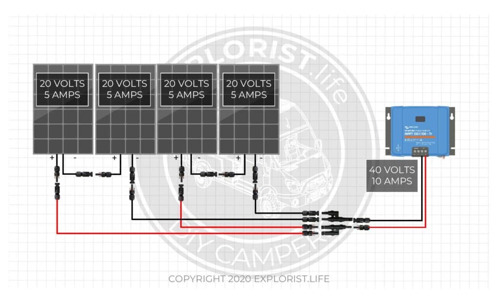
This diagram shows two, 5 amp, 20 volt panels wired in series. Since series wired solar panels get their voltages added while their amps stay the same, we add 20V + 20V to show the total array voltage and leave the amps alone at 5A. There is 5 Amps at 40 Volts coming into the solar charge controller.
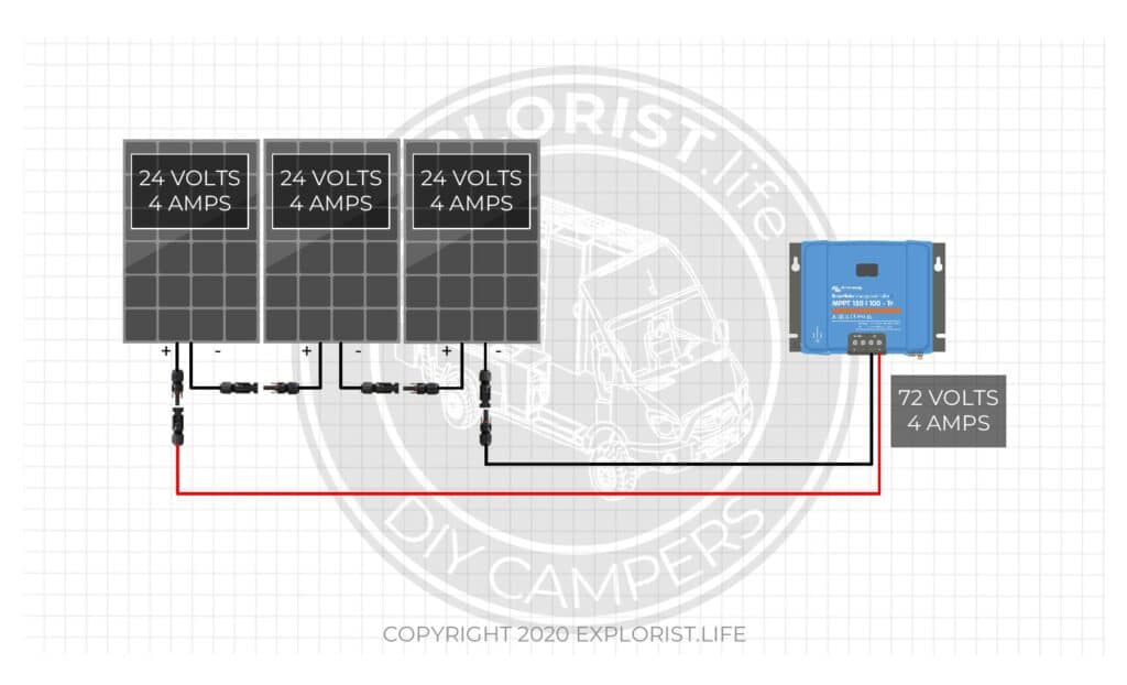
This diagram shows three, 4 amp, 24-volt panels wired in series. Since series wired solar panels get their voltages added while their amps stay the same, we add 24V + 24V + 24V to show the total array voltage of 72 Volts while the Amps remain at 4 Amps. This means there are 4 Amps at 72 Volts coming into the solar charge controller.
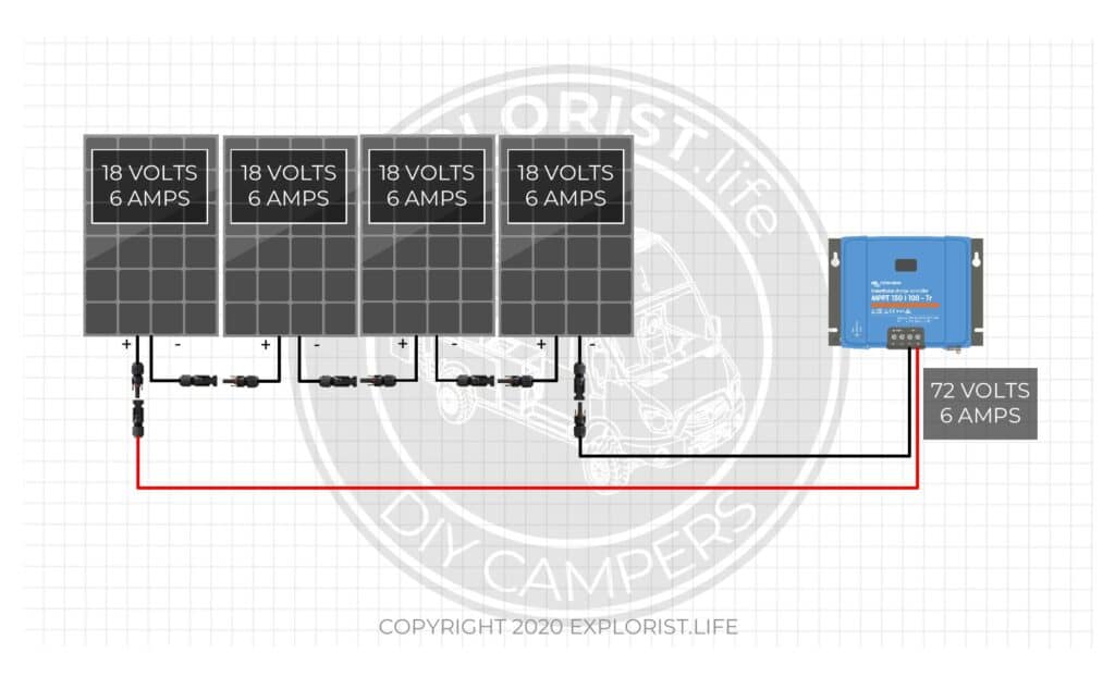
This diagram shows Four, 6 amp, 18-volt panels wired in series. Since series wired solar panels get their voltages added while their amps stay the same, we add 18V + 18V + 18V + 18V to show the total array voltage of 72 Volts while the Amps remain at 6 Amps. This means there are 6 Amps at 72 Volts coming into the solar charge controller.
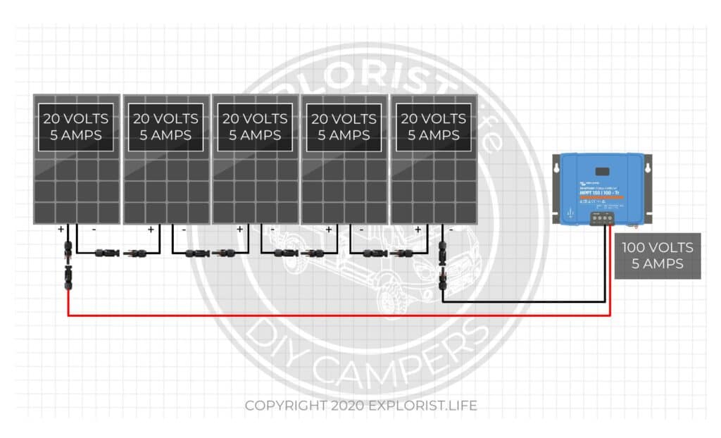
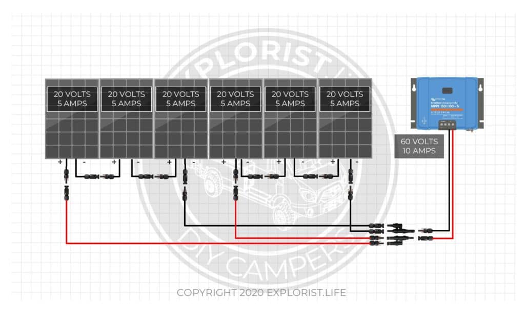
This diagram shows five, 5 amp, 20-volt panels wired in series. Since series wired solar panels get their voltages added while their amps stay the same, we add 20V + 20V + 20V + 20V + 20V to show the total array voltage of 100 Volts while the Amps remain at 5 Amps. This means there are 5 Amps at 100 Volts coming into the solar charge controller.
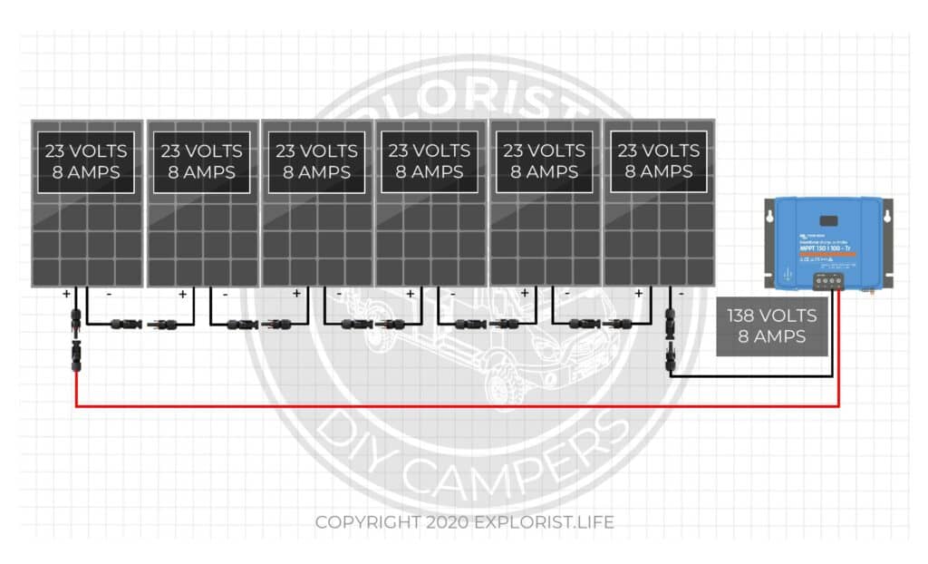
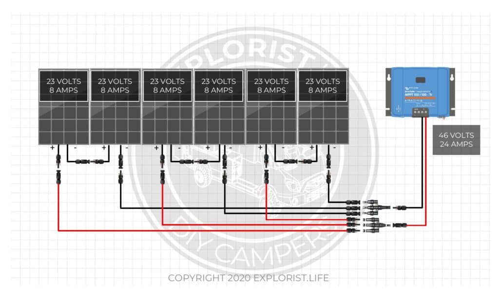
This diagram shows six, 8 amp, 23-volt panels wired in series. Since series wired solar panels get their voltages added while their amps stay the same, we add 23V + 23V + 23V + 23V + 23V + 23V to show the total array voltage of 138 Volts while the Amps remain at 8 Amps. This means there are 8 Amps at 138 Volts coming into the solar charge controller.
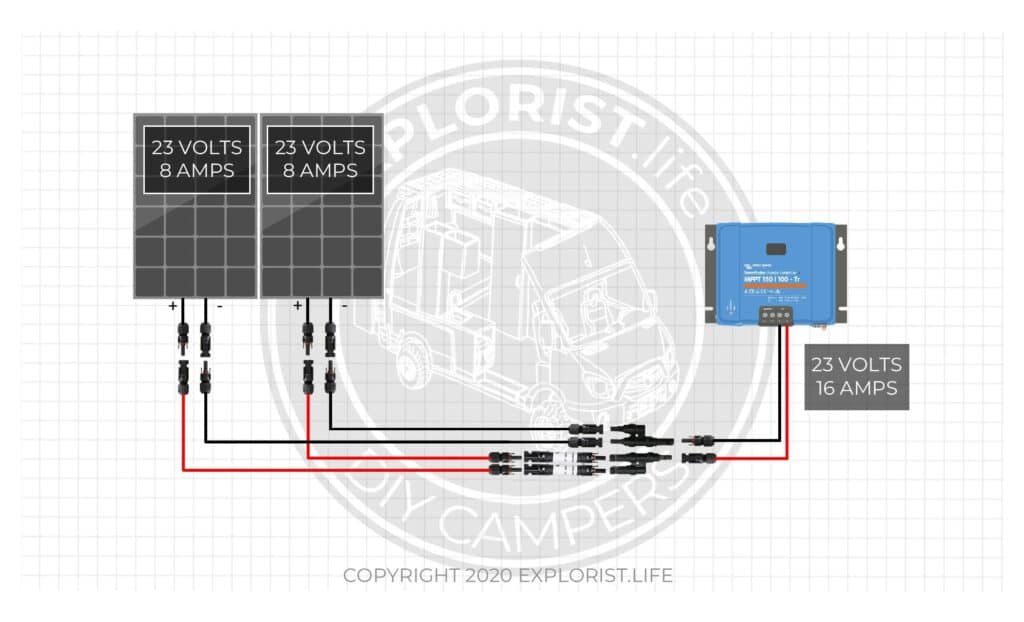
This diagram shows two, 8 amp, 23-volt panels wired in parallel. Since parallel wired solar panels get their amps added while their volts stay the same, we add 8A + 8A to show the total array amps of 16 Amps while the Volts remain at 23 Volts. This means there are 16 Amps at 23 Volts coming into the solar charge controller.
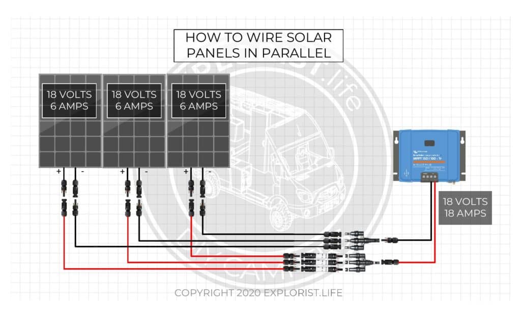
This diagram shows three, 6 amp, 18-volt panels wired in parallel. Since parallel wired solar panels get their amps added while their volts stay the same, we add 6A + 6A + 6A to show the total array amps of 18 Amps while the Volts remain at 18 Volts. This means there are 18 Amps at 18 Volts coming into the solar charge controller.
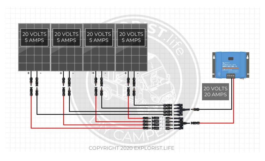
The above diagram shows four, 5 amp, 20-volt panels wired in parallel. Since parallel wired solar panels get their amps added while their volts stay the same, we add 5A + 5A + 5A + 5A to show the total array amps of 20 Amps while the Volts remain at 20 Volts. This means there are 20 Amps at 20 Volts coming into the solar charge controller.
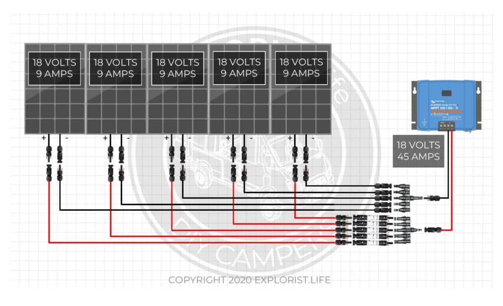
The above diagram shows five, 9 amp, 18-volt panels wired in parallel. Since parallel wired solar panels get their amps added while their volts stay the same, we add 9A + 9A + 9A + 9A + 9A to show the total array amps of 45 Amps while the Volts remain at 18 Volts. This means there are 45 Amps at 18 Volts coming into the solar charge controller.
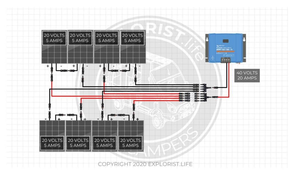
The above diagram shows a four-panel array using 5 Amp, 20 Volt panels wired in a series-parallel configuration of 2-panel series strings wired in parallel (2s2p). First, we need to find the volts and amps of the series wired strings of solar panels. Since solar panels wired in series add their voltages together while the amps stay the same, we add 20V + 20V. This means that each series string in this series-parallel configuration is 5 Amps at 40 Volts. Since the two 5A – 40V series strings are then wired in parallel, we add the amps while not changing the volts because parallel wired solar panels (or series strings) get their amps added while their volts remain the same. Adding 5A + 5A from the series strings and leaving the volts the same as the series wired strings gives us an array of 10 Amps at 40 Volts.
The above diagram shows a six-panel array using 5 Amp, 20 Volt panels wired in a series-parallel configuration of 3-panel series strings wired in parallel (3s2p). First, we need to find the volts and amps of the series wired strings of solar panels. Since solar panels wired in series add their voltages together while the amps stay the same, we add 20V + 20V + 20V. This means that each series string in this series-parallel configuration is 5 Amps at 60 Volts. Since the two 5A – 60V series strings are then wired in parallel, we add the amps while not changing the volts because parallel wired solar panels (or series strings) get their amps added while their volts remain the same. Adding 5A + 5A from the series strings and leaving the volts the same as the series wired strings gives us an array of 10 Amps at 60 Volts.
The above diagram shows a six-panel array using 8 Amp, 23 Volt panels wired in a series-parallel configuration of 2-panel series strings wired in parallel (2s3p). First, we need to find the volts and amps of the series wired strings of solar panels. Since solar panels wired in series add their voltages together while the amps stay the same, we add 23V + 23V. This means that each series string in this series-parallel configuration is 8 Amps at 46 Volts. Since the three 8A – 46V series strings are then wired in parallel, we add the amps while not changing the volts because parallel wired solar panels (or series strings) get their amps added while their volts remain the same. Adding 8A + 8A + 8A from the series strings and leaving the volts the same as the series wired strings gives us an array of 24 Amps at 46 Volts.
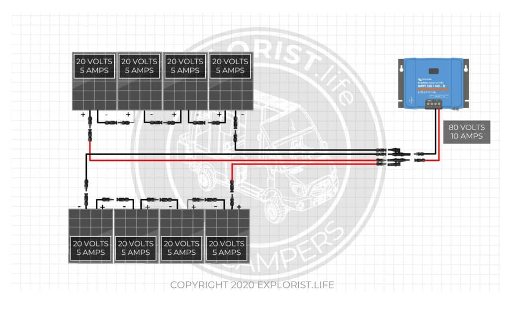
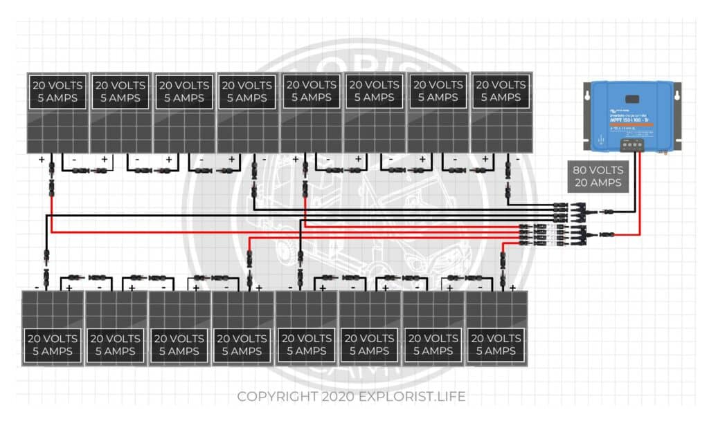
The above diagram shows an eight-panel array using 5 Amp, 20 Volt panels wired in a series-parallel configuration of 4-panel series strings wired in parallel (4s2p). First, we need to find the volts and amps of the series wired strings of solar panels. Since solar panels wired in series add their voltages together while the amps stay the same, we add 20V + 20V + 20V + 20V. This means that each series string in this series-parallel configuration is 5 Amps at 80 Volts. Since the two 5A – 80V series strings are then wired in parallel, we add the amps while not changing the volts because parallel wired solar panels (or series strings) get their amps added while their volts remain the same. Adding 5A + 5A from the series strings and leaving the volts the same as the series wired strings gives us an array of 10 Amps at 80 Volts.
Check your Comprehension
Here is a quiz you can take to check yourself and see if you understand this blog post:

74 Responses
Can I wire one string in series and one string in parallel to a combiner box then to my inverter? My inverter manual shows that the best set up to get my max out of the unit is to wire 8 panels in series and 2 in parallel. That is 2 different strings but I don’t know how to combine them?
How to wire solar panels in series-parallel: https://youtu.be/b2H8vpj8rQg
There is definitely alot to learn when it comes to hooking up your own solar system….. amps volts watts ect ect ect….. the solar wire diagrams make all the difference when it comes to the solar way of life…… ive noticed no one else has done that and thats were i was stuck….. what would us beginner’s do without the help of pros like you…. very helpful thank you….. oil companies watch out…..
I am wondering:
I will be using 3 x Solaria PowerXT-400R-PM
Vmp: 42.4V
Imp: 9.41A
Voc: 51.1V
Isc: 9.82A
Wired in series the recommended mppt charger is 250/85 Tr @$834
Wired in Parallel the recommended mppt charger is 100/50 @$323
Is there an efficiency advantage to wiring in series as opposed to parallel to justify the more than doubling in cost of the charge controller?
The battery bank is a 24v 400AH LiFePO4
Any input is appreciated
You want your solar array charging voltage to be at least 20V higher than your battery bank charging voltage. So… Your 24V battery bank will charge at about 28.8V and those panels wired in parallel are operating at 42V; so only 14V higher than the battery bank charging voltage. So… that’s too low for optimal MPPT performance and I’d have to recommend wiring in series with the $$$$$ controller.
Thank you for putting all this together, I appreciate it.
I like the quiz idea. I seem to pay more attention/focus on the content.
I saw this video/blog referenced on your fusing video. When you’re doing this calculations are you using Imp, Isc, or something else you’re calculating based on coldest temp? Presumably when calculating the total array short circuit current you use Isc and the rest of the time you use somtehing else?
Love these videos so far. Very helpful.
Imp when determining actual max power output. Isc when determining fusing needs.
Great explaination Thanks
Great stuff
I like the quiz. I did get one wrong but see where my mistake was. This is very helpful. I’m so glad that Brian from Adventure Van Man mentioned your channel.
Loving all your content! This little test is super helpful as well! Thank you for all the work you put into this!!
Thank you for an excellent series of solar how-to for the good, safe installation. I bought a 400-watt Renogy starter kit; it doesn’t give any installation wiring diagrams for panels to the charge controller. You explained series, parallel, and series/parallel which allows me to know what’s necessary to complete the installation. Renogy supplied a 10 amp fuse but no explanation why.
This blog post will teach you when/how to fuse a solar array: https://www.explorist.life/how-to-fuse-a-solar-panel-array-and-why-you-may-not-need-to/
Thanks for all the videos that you have been sharing on youtube. It inspired me a lot because the importance of learning how to set up a solar energy system at home is very important for me and family. Where we live, we do not have any access to electricity. Many times we need energy to power lights home. Thanks once again.
Great! Glad it’s been helpful
Thanks for the videos and posts. We have 4 255w panels
Vmp: 30.2V
Imp: 8.43A
Voc: 37.4V
Iec: 9.00A
We initially purchased the Victron 150|35 MPPT, but now I am thinking I need the 150|100. I ran the numbers through Victron’s calculator but am a bit confused. Would it be 2 series 1 parallel? They do not allow you to run only series or only parallel with their calculator. Can you advise?
Thank you,
Holly & Dustin
Wire them in series-parallel. You’ll be in the ballpark of the SmartSolar MPPT 150/85 if you are attaching to a 12V battery bank: https://battlebornbatteries.com/product/victron-smartsolar-mppt-150-85-tr-charge-controller/?afmc=explorist_bb67 Here’s a video that will teach you how to size a charge controller: https://www.youtube.com/watch?v=MxziHKvTRh8
I have a 16 panel setup. What is the best way to wire in parallel? Are there connectors that can be used to wire pos. to pos.?
thanks,
ted
I would strongly advise against wiring 16 panels in parallel. You will be much better off with some kind of series-parallel configuration.
I am glad I found your series on Solar information. It takes the guess work out of what I am trying to put together. Great job!!! Love the Question/Answer part.
Aweosome! Glad it helped!
THANK YOU VERY HELPFULL
Glad it helped. 🙂
So informative,clear and concise!
Great! Glad it helped!
In the text explanation of the 2s2p array diagram, when totaling the volts and amps it reads “Adding 10 Amps + 10 Amps from the series strings and leaving the volts the same as the series wired strings gives us an array of 10 Amps at 40 Volts”.
This should read “Adding 5 Amps +5 Amps” etc.
Is this correct or am I totally befuddled?
Good catch. Yes. Typo fixed.
Thanks for the Quiz, it is very interesting!
Great! Glad it helped.
what is the size of the controller with the8 100w panels wire parralel-series, 40v-29a
Those are theorhetical panels, so it’s not good to base anything ‘in real life’ off of those values. But I have panel arrays and proper charge controllers at the bottom of this blog post under the ‘solar parts list’ header: https://www.explorist.life/3000w-inverter-400-600ah-400-to-1200w-solar-camper-solar-kit/
Thanks very interesting
Enjoyed the video good info. Question I have four Renogy 100 watt solar panels in series going into a 40amp mppt controller connected to four 6V 235AH Golf Cart Batteries. From there it goes into a 1000 watt inverter. I would like to increase the output of the system. I plan on getting a 3000watt inverter but not sure what else I need to have. Any suggestions? This system is on my fishing cabin.
Sure! Here is a diagram showing a system with a 3000w Inverter: https://www.explorist.life/3000w-inverter-400-600ah-400-to-1200w-solar-camper-solar-kit
I may have missed it. But is there an advantage to use a series or wire in parallel? Seems like parallel would be best because you get more charging amps?
You want your array voltage to be at LEAST 20V over your battery bank charging voltage. So… whatever wiring method it takes to get to that number. Amps on the solar panel side of the charge controller don’t really matter for output amperage. More info: https://www.explorist.life/solar-panels-series-vs-parallel/
Hi Nate, I have a Goal Zero Yeti 3000. I purchased 6 100w Renology monocrystalline compact panels. Can I wire these in a series-parallel configuration of 2-panel series strings wired in parallel? And would I need fuses?
I believe My Yeti has a max input of 50v, 50A and 600w.
Thank you
Anjelino
If wired like that… What would be your array voltage? Would that voltage exceed the maximum voltage input of the goal zero unit?
Can you confirm if the Nominal Power Current or Short Circuit Current amps should be used to calculate limits from the solar panel spec sheet? Should there be any buffer below the charge controller maximums? I suspect nominal power current should be used, but since is a little than short circuit current I wanted to clarify which to use. This is a great post. Thanks!
You actually only need to know array wattage and voltage. More info: https://www.youtube.com/watch?v=MxziHKvTRh8
Well done! Very clear and concise.
Thanks so much!
hello sir my name is abdullah and iam from pakistan great explanation sir i am trying to figure out series parallel and series-parallel from many days great work keep it up and thanks for teaching us.
Hi Nate, I have a question on series parallel and your calculator. I used the calculator and the long version of the formula to come up with some numbers, but here is where I have the question. When looking at the examples above (not talking temp coefficients for VoC or Pmax) In series, 4 – 20v/5a panels would be 80v @ 5amps. In parallel, the same panels would be 20v @ 20amps. As I understand series parallel with the same setup would net me 40v @ 10amps correct? I try putting two and two in the calculator for series/parallel, but I keep coming up with ~ 97amps. I have 4 – 315W panels. VoC is 40.29. Temp Coefficient VoC is -.33%. Temp for Pmax is -.23%. I estimate my lowest temp at -10F or -23C. I come up with series 187volts and 97.1 amps. When I change the configuration to show 2 panels series and 2 parallel, I only see the total voltage halved. What am I missing? I was expecting about 97V @ 48.6 amps or 100/50 MPPT controller for now. I am running a 12v system today, but will move to 48v w/all 6v batteries at some point. Can you tell me if there is something wrong here or do I need to do two calculations; one series and one parallel and then halve the highest values for series/parallel in 4 panel system?
The array voltage is cut in half as you noticed when you switched your 4x315w array from series to parallel. The amps did not change because on my calculator… the ‘amps’ figure is the amps that are coming OUT of the charge controller… not going into the charge controller.
@Nate Yarbrough, OK that makes more sense and apparently I missed that key point. So for input amps(from array), it doesn’t really matter for the controllers or did I miss that or is that just “wiring size” that is the concern? The simple formula I have used to size controllers is just total watts/DCv of battery bank. So if I have 6 x 315w = 1,890 watts. Divided by my end goal of 48vdc ~ 39.4 amps; so either 40 or 60A charge controller (allowing for some growth)should work? I am planning on series/parallel deployment with 10ga wiring.
That is indeed how you would size the charge controller for the proper amount of amps. The calculation for volts is a bit more complicated because if you are wanting to be precise, you need to account for temperature of the panel (as the temperature gets colder, the panel voltage goes up. More info: https://www.youtube.com/watch?v=MxziHKvTRh8
Nate – fist of all you rock, I have learnt so much from your videos – enough for me to start the concept of upgrading the system in the cottage now. I have a 12V system with 3000W (modified SW) inverter/charger with large battery bank of 2V each at aprox 1900AH each (17 years old now…) the panels are aprox 85 feet away with 2G wire. I’d like to upgrade to 3000W pure SW, new batteries at 2100AH each still using the 2V each to equal 12V. I’m looking at but not dead set on Canadian Solar HiDM 320W @ 44V Voc & 9.6A panels – I’m considering (4) panels wired as in one of the videos that you described Series/Parallel. I have copy/pasted your info with my numbers inserted. If I use a four-panel array using 9.6 Amp, 44 Volt panels wired in a series-parallel configuration of 2-panel series strings wired in parallel (2s2p). If I passed the attached test and understand the concept right I should be having 88V at 19.2A with 1689.6W heading back to the charge controller. With 2G wire at 85 feet I should be good. Would you mind verifying that I calculated it correctly and if you do not mind, what size MPPT charge controller I should be looking at. Or if you think my plan or any part of it is not the right one please tell me it is time to start over…Thank you for these videos it has been awesome watching!
Your 2 AWG wire will be more than sufficient at 85ft between panels & charge controller with 19.2A @ 88V. For sizing the charge controller with a 12V battery bank, though; you’ll actually need 2x charge controllers as the largest Victron Charge Controller (100A) can only handle array wattages up to 1450W; so you’d want to wire the array into two separate arrays feeding 2x charge controllers.
Hi there, your videos are extremely helpful o. YouTube, thank you.
I have 3 solar panels ad a Victron Mttp 100/15 controller.
Is it possible to wire 2 of the panels in series, and then connect them to the third panel in parralel. Reasons for this are:
1) I can’t accommodate more than three panels
2)I don’t want the whole array to be comprised if something goes wrong with o e part of it. E. G. I have heard that in a series system, if a shadow falls over one of the panels, the whole output is reduced.
Nope. You will have severe power loss if you wire like that. More info: https://www.explorist.life/using-mismatched-solar-panel-sizes/
If maximum solar output is desired, it’s best to avoid the shade. This is not as big of an issue as many people make it out to be.
Great explanations. I really like the quiz.
Great! Glad it helped. 🙂
I understand how series and parallel arrays work, what I don’t understand is what amps and volts you want going into the controller. My controller max amps is 50 and max volts is 150 which will be mounted 15 feet from panels. So what is the best amps and volts to wire the panels for?
Generally speaking, you want to feed the charge controller as many volts as the charge controller can safely handle and the amps will work themselves out as appropriate.
What specific panels are you using and I can give a better answer?
@Nate Yarbrough,
THANK YOU! for this answer.
I kept wondering what you meant by optimizing the voltage so the MPPT is working “effectively” and controlling “efficiently.”
Nate,
I like the quiz, it put the puzzle in a visual for me. Most of your diagrams are Series Parallel, my project is 2S, 7P I see how to wire it now, just need to find some 7 into 1 connectors.
I have never seen 7 to 1 mc4 combiners. The highest I’ve seen is 5-1. Usually, if there are 7 parallel strings; the amps from the array will be too high to be able to use MC4 connectors & 10 AWG Wire. I would be DESPERATELY trying to fit ONE more panel so I could run 3x series-strings of 5 panels (5s 3p) which would let me easily use a 3 to 1 combiner with 10 AWG wire.
Thank you,
You have a winner in this. I have been needing a tutorial and quiz-like this. I hope one of your former teachers finds it. Your info is a great thing for us sailors.
If you connect the solar panels in series to be able to run 10AWG instead of 6AWG from the array to the charge controller is it required for the batteries to be ran in series as well or can you leave it as 12V?
Great tutorial. Quick question on your Power Audit spreadsheet. I see it is 110v, how do I apply that to 220v Australian appliances?
Thank you
Shaun
It will work as-is with no alterations.
I’m a newbie to electrical and van life. I have a 2020 144” Sprinter and would like to go solar as much as possible for boondocking. I’m a fan of air conditioning and know I have limited roof space for MaxxAir vent as well as solar panels.
I see 12v, 24v, and 48v Air conditioning systems that don’t take up roof space at 90-100 lbs like roof 120 AC systems.
Do you recommend 48V systems for longer air conditioning use boondocking or is there a downside to 4 batteries in series with charging, step down to 12v use, etc?
Can a system be set up that charges from alternator, solar or shore?
I only recommend 24v battery banks for systems larger than 1200w of solar and larger than 3000w of Inverter power. If you are trying to run a 24v air conditioner or 48v air conditioner natively off of the battery bank, that’s fine; but you are, at that point, going to be diving into ‘electrical arts and crafts’ to make the system work as I have no resources at this time for 24/48v systems.
All of my diagrams charge from alternator, shore, and solar.
The quiz helped made push my thought process a bit and comprehend the puzzle.
Hi Nate. Looking to change my actual settings but not sure if it will fit so… here it is.
I actually have a Morningstar Mppt 60. Yep, probably not the one you’ve recommended…
The specs are 150 Voc max and 800 Watts on a 12 V battery bank.
I wonder if I can connect 3 panels in series (315 w, 40.7 VoC and 9.89 amps each). I know that VoC will be good (122.1 with some spaces for cold temperature).
But… Watts will be at 945 and system is 800 max. Can it be a problem ?
Also, cause if its a problem… can I install 4 panels with same specs as above, 2×2 (2xseries, 2xparallels) still on a 12v system… or must I absolutely convert my battery bank at 24v and buy a new converter (had it on 12v).
Regards,
Chantal.
Enjoyed the quiz. I thought it definitely strengthened my comprehension of the series/parallel concept.
Thanks !!
Great! Glad it helped!
many thanks, I enjoyed the quiz
regards Jay
Awesome! Glad it helped! 🙂
Nate … thank you – your information is the best on the web ! Question : I bought a Bluetti 150 that lists max input of 10 amps and 60 volts. I jumped the gun and ordered 4 new Newpowa 100 watt 12 volt panels. To correctly figure the volts is it 12 – or – as it lists on the back sticker
“Operating voltage 17.68 volts”. ? If it’s 12 I could hook up 4 in series and still be under the 60 volt limit.
If I do a 2+2 series/parallel since each panel is 5.66 amps – i’d be over the amp limit. Virtually all the 100 W panels I find are over 5 amps – how are people on line hooking up
4100 watt panels I’ve seen on 2 sites ? Thank You !!
You want to refer to the Open circuit voltage on the back of the panel to determine it’s max voltage output. Furthermore, as a panel gets colder, it will put out MORE voltage. See this video for more of an explanation: https://www.youtube.com/watch?v=MxziHKvTRh8
I don’t know how others are hooking up 4x100w panels. I have not really messed with the Bluetti system before. Just by your description; they are likely ignoring the maximum parameters of the unit.